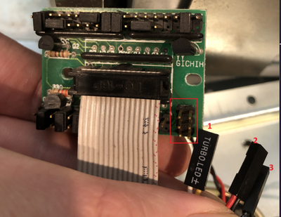
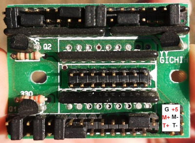
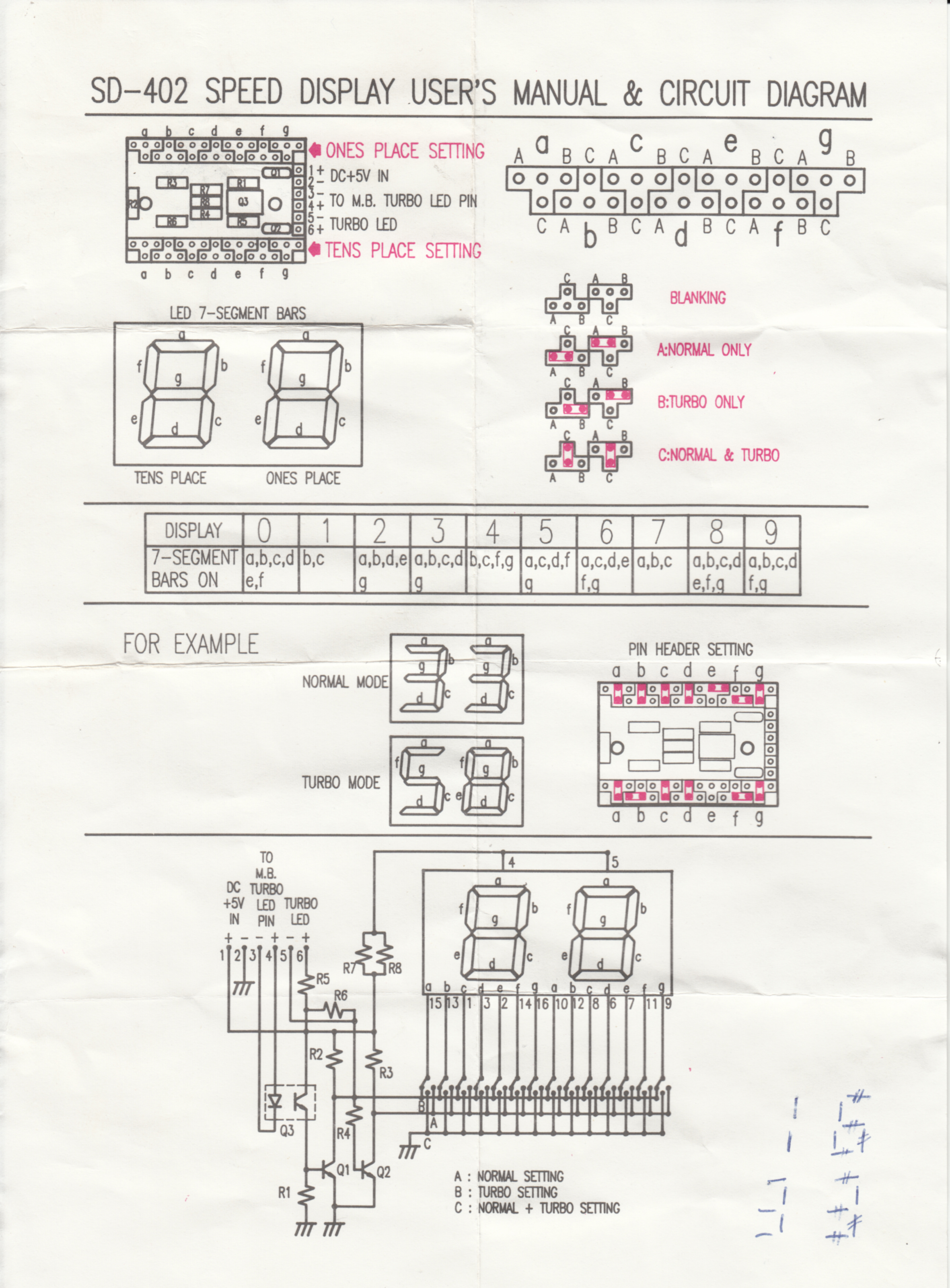
Ok, so I can't see enough to be sure of the wiring, but my guess for the connections is in the picture below. GND and +5V go to the top row, M+ and M- go to the motherboard turbo LED header, then T+ and T- can go to a case LED turbo indicator.
The GND and +5V are based on the +5V pin going to pin 1 of the cable to the LED display and the GND pin going to each of the 'C' pins of the segment selectors, so those segments would be on all the time, not switched through the transistors. It looks like the middle row might be an input to two of the transistors, which I think would be one transistor to control selected LED segments and another to control a case LED, so I think that's the switch input from the motherboard. The bottom row looks like it might be an output from one of those transistors, so probably the output to an external LED.
There are several guesses in that, but that also fits with the pins 1-6 described in that instruction sheet I linked to before.
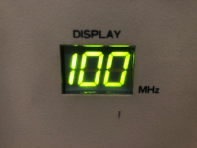
Before trying to plug anything in, you'll want to fix the jumpers for the segment selections (use those instructions as a guide). The top set in particular look wrong to me. I think the bottom set are ok and should switch from a 3 to a 7. Once that's fixed then try just connecting the +5V and GND and see if the display lights up. It's possible that using a bit of wire between the M- pin and either the +5 or GND pin then you might be able to test if the display changes.
So not certain about it, but best guess...
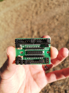
Also, there's a fair bit of silkscreen markings, so there might be some markings to be seen if you remove the 6 pin connector.
