VOGONS

Common searches


Reply 20 of 39, by carlostex

User metadata
Rank l33t
Rank
l33t

IMO the best way to go is to use the same specs the motherboard came in. If we're recapping a Socket 7 motherboard which can support CPU's up to 3.5V then 6.3V is a far more safe value for VRM low. 6.3V is also a good value for 486 boards.

Reply 21 of 39, by PhilsComputerLab

User metadata
Rank l33t++
Rank
l33t++

That makes sense. Now if a SS7 board has all 25V capacitors, I take it I wouldn't have to worry much about this. They might have chosen them based on availability or price?

How does one identify VRM high caps.

On newer boards there are always a few tall ones, rated at 16V, they mus the me the VRM high caps?

Close nearby (around the CPU socket) are also tall 6.3V caps, are these the ones for Vcore?

YouTube, Facebook, Website

Reply 24 of 39, by gdjacobs

User metadata
Rank l33t++
Rank
l33t++
PhilsComputerLab wrote:

Ok this starting to make sense now.

To summarise, if a polymer replacement has significantly lower ESR, then I get away with using a lower uF. Voltage has to match though.

Depends what it's used for. Ripple suppression is more closely associated with ESR while bulk filter caps (after a switching transistor or rectifier) require relatively large capacitance for charge storage (although higher switching rates require less). Also, using polymers as filter caps immediately after a switch mode VRM may allow for a resonance condition causing excessive voltage anomalies.

Ripple removal is addressed in the eponymous section of the Nichicon FP-Cap application guide.
http://www.nichicon.co.jp/english/products/pd … _catalog_05.pdf

All hail the Great Capacitor Brand Finder

Reply 25 of 39, by Dreamer_of_the_past

User metadata
Rank Oldbie
Rank
Oldbie
mockingbird wrote:

These days, you're limited to the diminishing supply of UESR caps from Nichicon, who stopped production last year or so.

So what exact models of capacitors for Pentium II-III-IV era computers we should stack up while we still can? Also, interested in those manufactured by Panasonic.

Reply 26 of 39, by PhilsComputerLab

User metadata
Rank l33t++
Rank
l33t++

I ordered a set of caps for a S939 board. I went with Panasonic throughout, but for the VRM 12V and Vcore I went with polymer.

YouTube, Facebook, Website

Reply 27 of 39, by gdjacobs

User metadata
Rank l33t++
Rank
l33t++
PhilsComputerLab wrote:

I ordered a set of caps for a S939 board. I went with Panasonic throughout, but for the VRM 12V and Vcore I went with polymer.

Polymer are likely the best option for ultra low ESR.

All hail the Great Capacitor Brand Finder

Reply 28 of 39, by 640K!enough

User metadata
Rank Oldbie
Rank
Oldbie
mockingbird wrote:

You will have to drop the capacitance though, especially on the VRM high where you always need a 16V cap for the 12V input. So typically, for VRM high caps where there's space for only an 8mm part, you use something like 16V 270uF (whereas you'd use 16V 1000uF with an electrolytic).

Can someone explain why we are talking about using lower capacities with polymer capacitors? Is it just that they are physically larger (wider, rather than tall), and therefore the same capacity as the electrolytic being replaced won't fit, or is there a more technical reason behind it?

mockingbird wrote:

Having said that, the theory behind using polymer caps in these types of VRMs is that you lose nothing by halving the capacitance because lower ESR is more important.

Is that always the case? Is it not a better idea to either replace with the same type, capacity and at least a safe voltage rating, or check the datasheet for the regulators used? I seem to remember the datasheet for an IC I used a few years ago stating something like, "capacitor C2 must not have an ESR less than x".

Reply 29 of 39, by gdjacobs

User metadata
Rank l33t++
Rank
l33t++
640K!enough wrote:

Is that always the case? Is it not a better idea to either replace with the same type, capacity and at least a safe voltage rating, or check the datasheet for the regulators used? I seem to remember the datasheet for an IC I used a few years ago stating something like, "capacitor C2 must not have an ESR less than x".

Generally this depends on the configuration of the feedback loop.

All hail the Great Capacitor Brand Finder

Reply 30 of 39, by 640K!enough

User metadata
Rank Oldbie
Rank
Oldbie
gdjacobs wrote:

Generally this depends on the configuration of the feedback loop.

What I was trying to ask is whether it is advisable (or even safe) to indiscriminately replace capacitors with lower-ESR parts, or parts with lower ratings, as mentioned above. Your response seems to confirm this, but depending on the structure of the circuit, there can be requirements for ESR to be within a certain range or for a specific capacitance in order to maintain stability, control ripple, etc., correct?

Reply 31 of 39, by Jepael

User metadata
Rank Oldbie
Rank
Oldbie
640K!enough wrote:
mockingbird wrote:

You will have to drop the capacitance though, especially on the VRM high where you always need a 16V cap for the 12V input. So typically, for VRM high caps where there's space for only an 8mm part, you use something like 16V 270uF (whereas you'd use 16V 1000uF with an electrolytic).

Can someone explain why we are talking about using lower capacities with polymer capacitors? Is it just that they are physically larger (wider, rather than tall), and therefore the same capacity as the electrolytic being replaced won't fit, or is there a more technical reason behind it?

I would say mostly it's because polymer electrolytic capacitors that have same capacitance and voltage rating are just physically larger than standard low ESR aluminium electrolytic capacitors.

640K!enough wrote:
mockingbird wrote:

Having said that, the theory behind using polymer caps in these types of VRMs is that you lose nothing by halving the capacitance because lower ESR is more important.

Is that always the case? Is it not a better idea to either replace with the same type, capacity and at least a safe voltage rating, or check the datasheet for the regulators used?

In an ideal world, a capacitor would have no series resistance (ESR which basically means how much the voltage will drop compared to an ideal capacitor when you draw current out of it) and no series inductance (ESL which basically means when you start pulling the current, how fast you are able to get it compared to an ideal capacitor).

Computer motherboards and many other devices have switching mode regulators. Basically depending on the switching frequency and max ripple voltage at maximum load, it only needs a certain minimum amount of capacitance at the VRM output that can be calculated to get the ripple below specified level that is necessary. Since there is ESR in real capacitors, it contributes to the ripple voltage, and thus you need to increase capacitance to get total ripple from capacitance and ESR below the specified level. That's why there are multiple capacitors on motherboard CPU voltage so that their ESRs and ESLs are paralleled to get lower ESR and ESL. So purely based on that, since polymer electrolytic capacitors do have smaller ESR (won't estimate how much), it means you can get off with smaller capacitance or fewer capacitors, as long as the total ripple is still below the required level.

It also basically means that you cannot take a look at switching mode regulator datasheet for example values, as they are just example values for example situations. When you are powering a CPU, you must know how much ripple voltage the CPU tolerates and then calculate how much capacitance you need to be safely below that level, given that you know the capacitor ESR and ESL as well. And then you get to choose the most economical way of achieving that goal, for example whether with a single expensive 10000uF ultra low ESR cap, or ten el cheapo 1000uF normal ESR caps.

So, halving the capacitance means doubling the capacitance ripple, so if ESR is low enough, it might compensate for it - but there will be a limit.
On the VRM input side, it may not be so sensitive.

640K!enough wrote:

I seem to remember the datasheet for an IC I used a few years ago stating something like, "capacitor C2 must not have an ESR less than x".

That is typical limitation for LDO linear regulators, their feedback loop goes unstable if capacitor ESR is too low. Normal linear regulators usually don't have this limit.

So you kind of need to know the purpose of the circuit you are replacing the capacitors, whether it will improve, make it worse or does not really matter much.
For example blindly recapping a noisy old sound card with ultralow ESR superpolymers usually does not make it less noisy or otherwise sound better than recapping it with normal electrolytics.
Just like new super low ESR car battery won't make an old rusty car any faster even if can provide more current to crank the starter motor.
In some circuits lower ESR will make currents larger so some other parts may run hotter.

Usually the problem is elsewhere in the circuit design that makes it noisy. And for example speaker outputs don't get improved much if DC blocking caps of 0.080 ohm are replaced with 0.008 ohm caps, when the speaker impedance is 8 ohms.

Oh, and many times it seems that people only talk about electrolytic capacitors. There are other kind of capacitors as well that are also important in circuits, but recappers only seem to be mostly worried about the electrolytics.

Reply 32 of 39, by gdjacobs

User metadata
Rank l33t++
Rank
l33t++
640K!enough wrote:

What I was trying to ask is whether it is advisable (or even safe) to indiscriminately replace capacitors with lower-ESR parts, or parts with lower ratings, as mentioned above. Your response seems to confirm this, but depending on the structure of the circuit, there can be requirements for ESR to be within a certain range or for a specific capacitance in order to maintain stability, control ripple, etc., correct?

Yes. Replacing Nichicon ultra low ESR caps with polymers is closer to a straight across swap, but a more radical upgrade might impact the stability and transient response of your PSU.

See this short paper for an explanation:
http://www.kemet.com/Lists/TechnicalArticles/ … 20Too%20Low.pdf

Jepael wrote:

I would say mostly it's because polymer electrolytic capacitors that have same capacitance and voltage rating are just physically larger than standard low ESR aluminium electrolytic capacitors.

Comparing two otherwise physically identical electrolytic capacitors and varying only case height, you will see an increase in capacitance, decrease in ESR, and increased thermal dissipation per degree of excess internal temperature (due to the larger surface area of the cap). The changes in ESR and thermal dissipation both have positive influences on ripple capacity and current handling, and this can result in longer capacitor lifetime than the shorter cans given the same operational currents.

So, sometimes higher capacitance electrolytic capacitors are used to achieve higher capacitor lifetime.

All hail the Great Capacitor Brand Finder

Reply 33 of 39, by Jepael

User metadata
Rank Oldbie
Rank
Oldbie
gdjacobs wrote:

Comparing two otherwise physically identical electrolytic capacitors and varying only case height, you will see an increase in capacitance, decrease in ESR, and increased thermal dissipation per degree of excess internal temperature (due to the larger surface area of the cap). The changes in ESR and thermal dissipation both have positive influences on ripple capacity and current handling, and this can result in longer capacitor lifetime than the shorter cans given the same operational currents.

So, sometimes higher capacitance electrolytic capacitors are used to achieve higher capacitor lifetime.

Yes, and there's another trick you can use. Sometimes higher voltage capacitors are used while keeping same capacitance for the exact same effect - larger size, decrease in ESR, better thermal, larger ripple current handling.
Downside is that this will most likely cause capacitor diameter to grow, but the good thing is that in some cases it can bring the height down as well, which is in handy in tight spaces.

Reply 36 of 39, by shamino

User metadata
Rank l33t
Rank
l33t
ahtoh wrote:

Has anyone had success with replacing the caps on older Super Socket 7 motherboards?
I have some concerns about ESR being too low compared to the original crappy caps.

I don't think that tends to be a problem with motherboards. I haven't recapped many Socket 7 boards (only 2 that I can think of), but the socket 7s both worked fine with newer/lower ESR caps installed than originals.

On occasion I've tried some extremely low ESR (but also much lower in capacitance) polymer caps on the Vcore rail of a few slot-1, socket 370, and mPGA478 boards and all of those worked great afterwards. Never tried polys with socket-7.

Reply 37 of 39, by ahtoh

User metadata
Rank Member
Rank
Member

When you say "extremely low ESR" what mOhm range do you think of?
I'm going to recap with 5mOhm polys, and there is a risk that voltage regulator will oscillate https://www.eetimes.com/document.asp?doc_id=1225555

Reply 38 of 39, by shamino

User metadata
Rank l33t
Rank
l33t
ahtoh wrote:

When you say "extremely low ESR" what mOhm range do you think of?
I'm going to recap with 5mOhm polys, and there is a risk that voltage regulator will oscillate https://www.eetimes.com/document.asp?doc_id=1225555

The most extreme poly swap I've done was on a couple of slot-1 boards. One was a 440BX, the other a VIA 694X.
The replacement caps I put on the Vcore of those boards were rated at 7mOhm. I don't have data on the originals, but I would guess they were comparable to Rubycon YXG at that period of time. Proceeding from that assumption, the originals might have been in the 50-60mOhm range when new.

I've never tried to check Vcore rails on a scope, but both boards worked perfectly in stress testing afterward. At minimum I would have been testing them with a P3-600E overclocked to 800/133 (it's a CPU that I routinely run that way). I have a Celeron 1.1GHz on a slocket which I think I also tested on the 440BX board.

Less extreme was another pair of 440BX boards whose replacement Vcore caps were rated 14mOhm. The first of these was a long time ago but my notes say it was tested with the Celeron 1.1GHz. Actually that board was the reason I bought that CPU - I wanted to make sure the poly swap was really working and needed something to stress it with.
The 2nd was a slot-1 BE6-II which I've definitely used with the Celeron and also the overclocked 800/133.

I've never tried polys anywhere outside of Vcore.
If you try polys, be aware that they typically have thick leads, so they can be harder to install. You really need to get the holes cleared.

=====
I've only looked close at the VRM of one super-7 board. But from what I remember, I think it was designed a bit differently (more simply) than any of the slot-1 and later boards I've seen. Unless I misunderstood, my super-7 board just has a single MOSFET to pull Vcore up, but nothing to pull it down other than the CPU's own current draw.
I don't know if this represents an important difference in design that would make my slot-1/370 anecdotes irrelevant.

Reply 39 of 39, by ahtoh

User metadata
Rank Member
Rank
Member

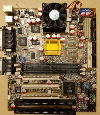
Done. Replaced all capacitors.
The board works fine, checked for oscillation using oscilloscope.

Digikey p/n below:

Index	Quantity	Part Number	Manufacturer Part Number	Description	Customer Reference	Backorder	Unit Price	Extended Price
1 10 493-1812-ND UPW1E220MDD6 CAP ALUM 22UF 20% 25V RADIAL 0 0.16300 $1.63
2 10 493-3697-ND RR50J821MDN1 CAP ALUM POLY 820UF 20% 6.3V T/H 0 0.55100 $5.51
3 17 493-3718-ND RR71C331MDN1 CAP ALUM POLY 330UF 20% 16V T/H 0 0.64200 $10.91
Subtotal $18.05

Attachments

  • Recapped.jpg
    Filename
    Recapped.jpg
    File size
    246.9 KiB
    Views
    1505 views
    File license
    Fair use/fair dealing exception