VOGONS


First post, by Kahenraz

User metadata
Rank l33t
Rank
l33t

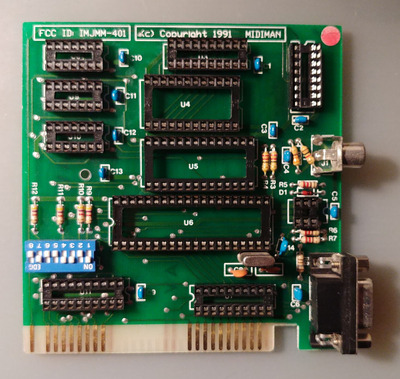
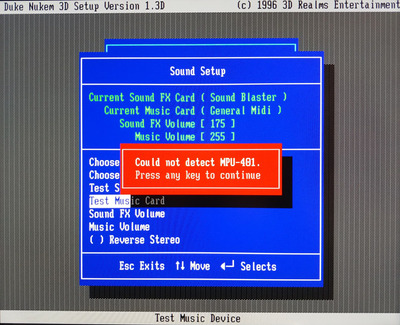
I have a couple of these Midiman MPU401 ISA cards and one if them is broken with the fault being that the card is not detected. This error can be demonstrated with the Duke3D setup.

IMG_20211115_192017_resize_52.jpg
Filename
IMG_20211115_192017_resize_52.jpg
File size
631.15 KiB
Views
1167 views
File license
Public domain

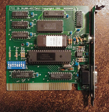
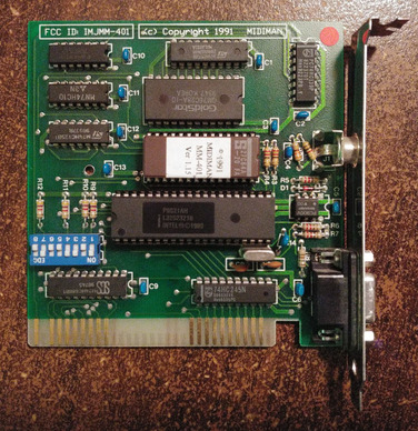
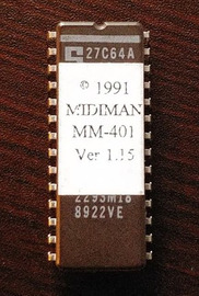
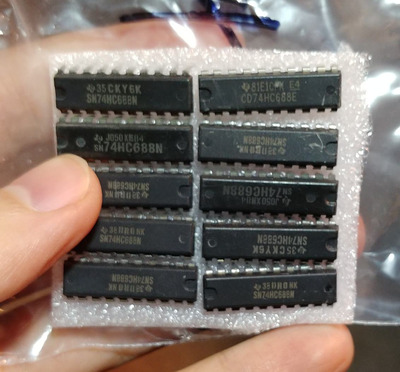
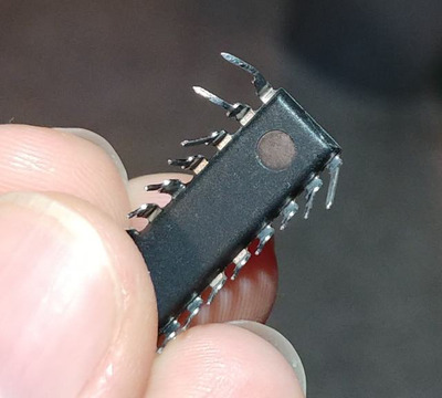
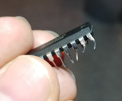
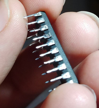
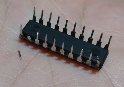
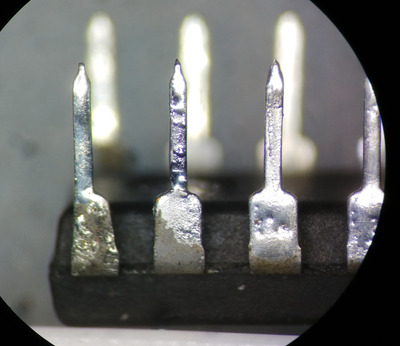
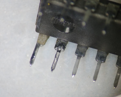
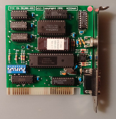
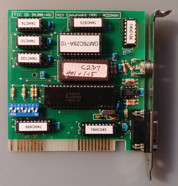
I found that the 74HC74AP chip (top left) would get extremy hot which is not characteristic on any of the working cards. I replaced this chip and it no longer gets hot but the cards remains undetected. I also swapped the two large socketed chips in the center which includes the ROM and confirmed that they are working fine. I also applied de-oxit to the socket pins and tested continuity with their solder points on the board. I found no obvious shorts between any of the resistors or capacitors and there is no visible damage to the board.

I'm not sure what else to do other than start replacing chips one at a time.

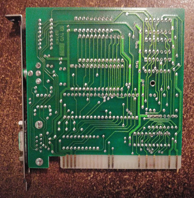
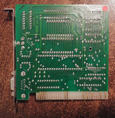
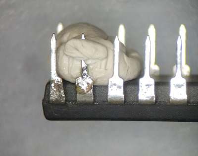
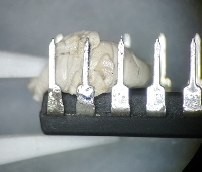
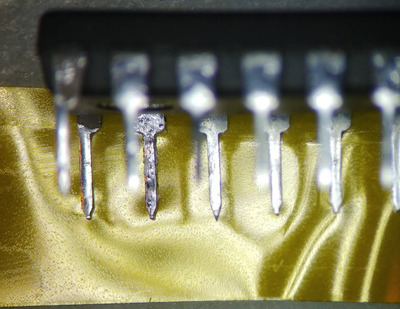
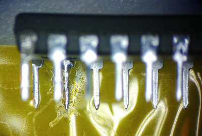
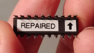
Here are some photos of the cards. They are otherwise identical but I have marked the problem card with a small red sticker.

IMG_20211115_191946_resize_18.jpg
Filename
IMG_20211115_191946_resize_18.jpg
File size
659.75 KiB
Views
1167 views
File license
Public domain
IMG_20211115_191912_resize_36.jpg
Filename
IMG_20211115_191912_resize_36.jpg
File size
742.85 KiB
Views
1167 views
File license
Public domain
IMG_20211115_191845_resize_51.jpg
Filename
IMG_20211115_191845_resize_51.jpg
File size
709.27 KiB
Views
1167 views
File license
Public domain
IMG_20211115_191824_resize_63.jpg
Filename
IMG_20211115_191824_resize_63.jpg
File size
715.96 KiB
Views
1167 views
File license
Public domain

Reply 1 of 16, by darry

User metadata
Rank l33t++
Rank
l33t++

I am no expert at this, but if you have a access to a scope (or maybe a decent logic probe), you could start comparing signals between a working and a non working card . This might give you a hint as to what is wrong .

Reply 3 of 16, by Kahenraz

User metadata
Rank l33t
Rank
l33t
darry wrote on 2021-11-16, 03:23:

I am no expert at this, but if you have a access to a scope (or maybe a decent logic probe), you could start comparing signals between a working and a non working card . This might give you a hint as to what is wrong .

I do have a scope. Unfortunately, I don't have any experience using it for these kind of diagnostics.

AppleSauce wrote on 2021-11-16, 03:30:

That Goldstar chip appears to be SRAM , maybe it's gone bad?

I've been working my way across both boards, socketing chips as I go. So far I have found that the replacement 74HC74 was good but 74HC10 below it was also bad. This produced the same error as the bad board when swapping only this chip but there is still some other problem that is still causing it to fail even after replacing this chip as well.

I tasted the SRAM and that checked out fine. Still a couple more to go...

Reply 4 of 16, by Kahenraz

User metadata
Rank l33t
Rank
l33t

The 74HC688 was also bad. I wonder what kind of fault had to occur to cause so many chips to die. It seems to be isolated to the left side of the board.

I've run out of sockets and I don't want to solder any of these back directly onto the board so I can't confirm if this is the last faulty chip. The 74HC573 and 74HC245 also tested fine. The only IC I haven't tested specifically is the 74HC139 and the PC900V DAC. I am also assuming that the crystal is working. The rest are all passive components.

Reply 5 of 16, by keropi

User metadata
Rank l33t++
Rank
l33t++

most likely some power supply failure caused this
PC900V is an optocoupler for the MIDI-IN signal, it will not cause this failure if it's bad
you can test the card without it just to make sure

🎵 🎧 PCMIDI MPU , OrpheusII , Action Rewind , Megacard and 🎶GoldLib soundcard website

Reply 7 of 16, by Kahenraz

User metadata
Rank l33t
Rank
l33t

Still waiting on one more chip for the repair. I ordered these in November and the ETA says February. Maybe it's stuck on a boat off the coast of California.

To pass the time I dumped the ROM. I found that it was identical to the one here.

I'm attaching it here for archival in case anyone ever needs a copy. I've also noted the kind of chip used and included a photo as well.

AMD27C64A.jpg
Filename
AMD27C64A.jpg
File size
43.54 KiB
Views
966 views
File license
CC-BY-4.0

Attachments

  • Filename
    MM401_1_15.zip
    File size
    67.56 KiB
    Downloads
    44 downloads
    File license
    Public domain

Reply 8 of 16, by Kahenraz

User metadata
Rank l33t
Rank
l33t

By "ETA" February apparently meant "will arrive tomorrow". I got the last set of chips in the mail the other day and I'm looking at them now. There is at least one casualty but hopefully the others are alright. This is why I like to order extras when buying old chips. You never know what condition they will arrive in and how many will actually work.

IMG_20211220_081237.jpg
Filename
IMG_20211220_081237.jpg
File size
27.11 KiB
Views
925 views
File license
CC-BY-4.0
IMG_20211222_052358_resize_58.jpg
Filename
IMG_20211222_052358_resize_58.jpg
File size
117.95 KiB
Views
925 views
File license
CC-BY-4.0
IMG_20211222_052414_resize_95.jpg
Filename
IMG_20211222_052414_resize_95.jpg
File size
149.22 KiB
Views
925 views
File license
CC-BY-4.0
IMG_20211222_053256_resize_68.jpg
Filename
IMG_20211222_053256_resize_68.jpg
File size
216.83 KiB
Views
925 views
File license
CC-BY-4.0

Reply 9 of 16, by Kahenraz

User metadata
Rank l33t
Rank
l33t

I found that three of the chips were damaged. One had its pins mangled, another had a pin break off while trying to straighten it, and a third got dented on a pin somehow.

IMG_20211222_055006_resize_38.jpg
Filename
IMG_20211222_055006_resize_38.jpg
File size
32.84 KiB
Views
905 views
File license
CC-BY-4.0
IMG_20211222_055022_resize_2.jpg
Filename
IMG_20211222_055022_resize_2.jpg
File size
34.65 KiB
Views
905 views
File license
CC-BY-4.0
IMG_20211222_055034_resize_59.jpg
Filename
IMG_20211222_055034_resize_59.jpg
File size
56.5 KiB
Views
905 views
File license
CC-BY-4.0
IMG_20211222_054954_resize_65.jpg
Filename
IMG_20211222_054954_resize_65.jpg
File size
40.42 KiB
Views
905 views
File license
CC-BY-4.0

Reply 10 of 16, by Kahenraz

User metadata
Rank l33t
Rank
l33t

I managed to straighten the pins on the other two and thought about what to do with the broken leg on the third. The chip could still be salvaged by running a bodge wire as necessary, but I felt it was a waste to not try and reattach it. This wouldn't be entirely useful if the chip is to be soldered as the leg would fall off on its own when heated again. But a bit of reinforcement with solder should hold it on well enough for use in a socket.

I didn't have any way to hold the leg and the chip in position with my soldering iron and solder wire in-hand so I propped it up and stuck it in place with some mounting putty and tacky flux. This was somewhat regrettable afterwards as it melted onto the back of the leg and had to be scraped off but I still managed to flow some solder well enough to keep it from moving. This wasn't the end of it though as it was only secured on one side with the break still through to the other.

After cleaning off the melted putty I held the chip down against some Kapton tape and fed in a bit more solder. This made a small blob which I then spread along the surface while holding the leg firmly with ceramic tweezers.

IMG_20211222_060135_resize_32.jpg
Filename
IMG_20211222_060135_resize_32.jpg
File size
73.63 KiB
Views
898 views
File license
CC-BY-4.0
IMG_20211222_060724_resize_63.jpg
Filename
IMG_20211222_060724_resize_63.jpg
File size
76.73 KiB
Views
898 views
File license
CC-BY-4.0
IMG_20211222_062537_resize_84.jpg
Filename
IMG_20211222_062537_resize_84.jpg
File size
145.59 KiB
Views
898 views
File license
CC-BY-4.0
IMG_20211222_061457_resize_0.jpg
Filename
IMG_20211222_061457_resize_0.jpg
File size
120.69 KiB
Views
898 views
File license
CC-BY-4.0
Last edited by Kahenraz on 2021-12-22, 13:32. Edited 4 times in total.

Reply 11 of 16, by Kahenraz

User metadata
Rank l33t
Rank
l33t

The result was excellent and the leg held firm, now secure on both sides of the break. A bit more solder on the outside surface would have been ideal but this was an extremely precise repair and any further manipulation could have easily made it worse. This was sufficient and I confirmed that it was a strong connection by inserting and removing it from a socket a few times.

Of course, there's no way I would remember that I had repaired this; which chip in a pile of chips and which leg on the thing. So as I always try to do, I added a helpful little note to myself. This is to remind me that if I use this chip to put it in a socket and not to solder it directly as this would cause the leg I just repaired to fall off. Which leg? The one with the arrow pointing to it, of course. 😀

IMG_20211222_062521_resize_60.jpg
Filename
IMG_20211222_062521_resize_60.jpg
File size
151.21 KiB
Views
898 views
File license
CC-BY-4.0
IMG_20211222_062442_resize_92.jpg
Filename
IMG_20211222_062442_resize_92.jpg
File size
64.87 KiB
Views
898 views
File license
CC-BY-4.0
IMG_20211222_064253_resize_43.jpg
Filename
IMG_20211222_064253_resize_43.jpg
File size
36.6 KiB
Views
888 views
File license
CC-BY-4.0
Last edited by Kahenraz on 2021-12-22, 13:35. Edited 6 times in total.

Reply 12 of 16, by Kahenraz

User metadata
Rank l33t
Rank
l33t

Since I was already adding sockets to a few of the chips I ended up just socketing everything on the board. This also will provide me with a good reference in case I ever need to swap chips again in the future for testing.

When socketing everything onto the board I had a moment of panic as I was immediately greeted by the same "Could not detect MPU-401" error -- which was a problem because I had already confirmed that the board was working before adding the rest of the sockets. But this was a false alarm! I had accidentally flipped the dip switch on position 2. After setting it back to the ON position everything worked perfectly. All of the chips I had ordered also tested fine with no defects in functionality.

Success! My Midiman MM-401 is repaired.

IMG_20211222_074754_resize_26.jpg
Filename
IMG_20211222_074754_resize_26.jpg
File size
258.35 KiB
Views
886 views
File license
CC-BY-4.0
IMG_20211222_071239_resize_1.jpg
Filename
IMG_20211222_071239_resize_1.jpg
File size
256.23 KiB
Views
886 views
File license
CC-BY-4.0
Last edited by Kahenraz on 2021-12-22, 16:03. Edited 1 time in total.

Reply 16 of 16, by Kahenraz

User metadata
Rank l33t
Rank
l33t
maxtherabbit wrote on 2021-12-22, 15:13:

tl;dr was the address decoder '688 the only thing wrong with this card?

It was three chips on the left side which failed: 74HC74, 74HC10, and 74HC688. Somehow 74HC125 survived whatever catastrophe occurred.

I knew something was wrong initially because not only did the card not detect but 74HC74 got very hot to the touch. This chip did not even get warm on my other working cards. Replacing this one chip did not fix the issue so I started swapping chips one by one. After socketing and swapping three chips down the left side and having it still not work I decided to socket the entire board. I found out later that there was only one more dead chip but I didn't know it at the time.

Here is a photo with most the chips labeled for reference. This is the second board I was using to swap chips with. Labeling them helped me keep track of which chip was what at a glance.

Note the hand-written sticker on the EPROM chip. I bought several cards from someone who used to work at M-Audio so this would have been written by either him or another engineer. The SRAM was already socketed on this board before I touched it so it might have been used for testing. I guess I finished the job by socketing everything else.

IMG_20211222_105311_resize_67.jpg
Filename
IMG_20211222_105311_resize_67.jpg
File size
242.36 KiB
Views
820 views
File license
Public domain