shock__ wrote:640K!enough wrote:shock__ wrote:Any input on that? I wouldn't mind adding a header or even a full implementation - but have to admit that I've never worked with SPDIF before, so some guidance might be required.
I have hardly ever used a S/PDIF-enabled device, much less designed anything involving one, but I question the feasibility of this endeavour. Looking through the datasheet and programmer's guide, it quickly becomes clear that it would be far more involved than setting a register once and connecting those signals to an appropriate encoder. The only way it seems even remotely feasible still involves going through the on-chip analogue stage before getting to the CODEC module. Otherwise, you seemingly won't have access to the full card's output. Furthermore, the serial output is unavailable when certain other FIFO modes are used, if I'm reading correctly, and would seemingly also require driver-level changes for Windows to manage that register setting. My vote would be to ask this person to provide some form of proof-of-concept implementation, or at least more concrete circuit and software design guidelines, before going ahead with unnecessary layout and routing work. I'm not claiming that it definitely can't be done, but it doesn't look like it would work as intended.
Thanks for the input - that is pretty much on par with my judgement.
I wish to bring you some of my observations and bring you a possible improvement of the ARGUS project. You heard about s/pdif and i2s a year ago and without enthusiasm I put that aside.
Here are some observations.
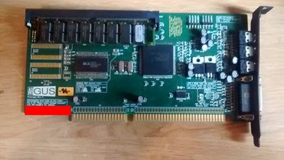
The Pin 60 of Am78c201akc on the Compaq Ultrasound 32 Pro sound card is wired to the P3 connector (i2s input/ouput?).
This card don't have a connector for a CDROM drive. So it is likely that this signal is ESPCLK.
After reading the following documents:
- AMDIS03767-1.pdf (datasheet)
- InterWave IC Am78C201-202 Programmer's Guide (1996) Revision 2
(page: 89 to 91, 189 to 190, 248, 279 to 280, 305 to 306)
- pnpddk - DDKMANUL.DOC
- Audio processing chip with external serial port - US5809466.pdf
(page: 50, 57, 58, 137 to 139, 160, 182 to 183)
https://patents.google.com/patent/US5809466A/en
Here are some advances:
1 / There are two functions of IWUTIL.EXE that can read (IwaveRegPeek) and write (IwaveRegPoke) a value in a register. IWUTIL.exe is a compilation of IWUTIL.C program (included in the pnpddk).
- Read the value of the ICMPTI register:
IWUTIL.EXE IwaveRegPeek ICMPTI
- Write a value in the ICMPTI register:
IWUTIL.EXE IwaveRegPoke ICMPTI, 0x9F
The value "0x9F" corresponds to:
serial transfer mode -> DSP Synthesizer data to external Serial port pins mode.
This mode should not have any impact on FIFO input and FIFO playback.
IWUTIL.EXE should be able to be executed when the card is initialized.
It should be checked if the analog audio output is still active in this mode.
This mode must be enough to enjoy 16bit samples at 44.1khz in digital quality (utopia sf).
2 / Here is an example of an i2s to s/pdif converter.
http://scan78.free.fr/Elektor/Elektor%202000% … 0FR/f00a038.pdf
https://www.elektormagazine.com/magazine/elek … or-200010/16866
With some additional analysis, we can check if the external serial port format of the AM78C201AKC corresponds to one of the seven formats supported by the CS8402, and how to manage the clock differences between the ESPCLK signal and the Master clock signal ( MCK) of the CS8402 (48fs versus 128fs).
I do not know enough about these differences. But, I am told that it would be interesting to inject the signals ESPSYNC, ESPCLK, ESPDOUT in one of the converters i2s to s/pdif of the same period and see how it behaves. I have in mind the i2s to s/pdif converter of the EWS64XL board (first checking if the voltage levels are compatible between Interwave and EWS64XL rack module).
3 / We tried to compile IWUTIL.C, but as we are not a computer developer we ran into compilation errors. And, we left that aside. Maybe one of you, more expert or luckier, will get there.
4/ But to go further in this analysis, we need simple and clean access to ESPSYNC, ESPCLK, ESPDOUT signals. (Leave aside the ESPDIN signal which seems more complex and less useful).
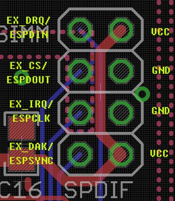
That's why I wanted to know if the space between the SIMM connector and the MPC connector is large enough to place a connector with 8 pins (a right angle 2x4pin male connector to wire a shielded cable like USB cable). ?
Pin 1 + 5v power
Pin 2 ESPDIN (pin41 - AM78C201AKC)
Pin 3 ESPOUT (pin61 - AM78C201AKC)
pin 4 Ground for power
Pin 5 + 5v power
Pin 6 ESPSYNC (pin54 - AM78C201AKC)
Pin 7 ESPCLK (pin60 - AM78C201AKC)
Pin 8 Ground for power
Project: SB-XXXL, Extensive Sound Cards System