
Reply 2361 of 3172, by 640K!enough
Rank
Oldbie
root42 wrote on 2020-06-10, 07:37:I think my DRAM soldering skills were suboptimal. 😀
Did you solder the ROM onto the board? It doesn't seem to have found that, either. It seems awfully suspicious that it found neither RAM nor ROM.
Reply 2362 of 3172, by root42
Rank
l33t
- Rank
- l33t
640K!enough wrote on 2020-06-10, 07:44:root42 wrote on 2020-06-10, 07:37:I think my DRAM soldering skills were suboptimal. 😀
Did you solder the ROM onto the board? It doesn't seem to have found that, either. It seems awfully suspicious that it found neither RAM nor ROM.
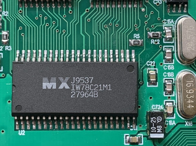
yes I think so. That's the MX chip, right? Maybe I need to reflow the side of the Interwave that speaks to RAM/ROM and check all traces and components in that path?
EDIT: that would be the 'upper' row of pins on the PCB, right? those lead to the octal latches (74act373).
Reply 2363 of 3172, by root42
Rank
l33t
- Rank
- l33t
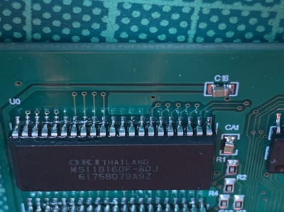
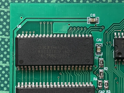
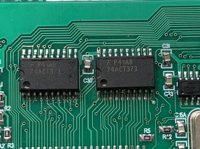
i reflowed everything, but I still get 0 DRAM detected. Can someone explain how the left part of the board works, how DRAM and ROM is accessed? I guess the latches play a role... And what's the tiny 8 pin IC near the latches?
Could be one of the ICs broken? And what does the ROM hold? Would that be visible in the iwinit output as well?
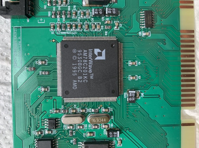
Edit: a couple of pictures of the ICs that I have doubts about.
Attachments
Reply 2364 of 3172, by 640K!enough
Rank
Oldbie
Let's start with the questions first:
root42 wrote on 2020-06-10, 08:22:yes I think so. That's the MX chip, right?
Yes, the Macronix IC is the mask ROM. It contains the 1 MiB instrument bank that is used for wavetable playback when in native InterWave mode. Because relatively few titles seem to support RAM-based banks on InterWave, that is, practically, the only instrument set that will be used in games.
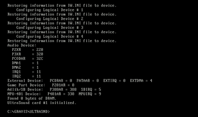
root42 wrote on 2020-06-10, 15:24:Would that be visible in the iwinit output as well?
Yes, IWINIT will report "Found ROM chip" followed by the bank number and name.
root42 wrote on 2020-06-10, 15:24:And what's the tiny 8 pin IC near the latches?
That is the serial EEPROM containing the Plug and Play resource map. From what you have told us, this appears to be working fine.
root42 wrote on 2020-06-10, 15:24:Can someone explain how the left part of the board works, how DRAM and ROM is accessed?
This is a bit of a strange question to answer, particularly since I am not familiar with the changes involved in going from ARGUS to Gusar Lite, so I will describe the concepts more in terms of a generic InterWave board. The chip has select lines for one of four banks; each bank can be up to 4 MiB, either RAM or ROM. ROM also gets a dedicated select line; when combined with clever use of other selection logic, this is used to distinguish between RAM and ROM, giving a total address space of up to 16 MiB of each. Since ROM doesn't use the multiplexed addressing scheme that DRAM does, the latches are used to store 16 bits of the address. Along with the remaining address lines driven by the the InterWave, there are a total of 22 address lines for the ROM. Hopefully that made at least a bit of sense.
So, in order to reach the ROM, the InterWave must be functional, as well as the latches and ROM IC itself. There is usually a little less involved in accessing DRAM. It is usually just between the InterWave, a few resistors and the DRAM chips (or modules) themselves. However, the SOJ packages can sometimes be a bit of a chore to solder perfectly.
Since your card appears to be partially functional, one test you can try is to use PLAY.EXE to play a simple WAV file. This does not need RAM or ROM; as long as the InterWave can be initialised and the analogue stage of the card is functional, you should get some sound. If that doesn't work either, you have more to worry about.
Now that we've gone beyond a few messages, it would probably be a good idea to split off the Gusar-related discussions to their own thread(s). I don't mind trying to help with trouble-shooting at all, but not if it completely derails the ARGUS discussion.
Reply 2365 of 3172, by root42
Rank
l33t
- Rank
- l33t
Thanks for the help! Yes, if a moderator could please spin off the last couple of messages in a new thread, that would be awesome!
EDIT: It doesn't play WAV files either. I hear clicking at the start and end of the play, but that's it.
See https://youtu.be/fpEegJYOKIU (turn up the volume for the click sounds)
Reply 2366 of 3172, by 640K!enough
Rank
Oldbie
root42 wrote on 2020-06-10, 17:50:EDIT: It doesn't play WAV files either. I hear clicking at the start and end of the play, but that's it.
I was beginning to doubt my own claims, so I re-installed my GUS PnP, SIMMs and ROM removed, just to confirm. As expected, PLAY.EXE does indeed play WAV files with no memory at all installed. In fact, I am listening to tracker files via Cubic Player, configured to use the CODEC module rather than the InterWave synthesiser for playback, as I type.
Just for the sake of completeness, can you try a longer WAV file. The idea is to see if it complains part of the way through, or thinks it's actually playing something.
I should have asked before, especially since you bothered to record a video, but can you also post the output of the SET command, to show your list of environment variables? Do you have a valid IW.INI as part of your installation? Can you post that as well? Lastly for now, is the InterWave board the only sound device in the system? If not, perhaps you should consider a different I/O address (currently 220H) and disable the Sound Blaster and Ad Lib emulation features, just to get rid of the unneeded complexity for now.
EDIT: I keep forgetting to mention that there are a few traces that look questionable just above the latches. You may want to have a closer look to make sure they are still intact. Also, if the residue from the flux you use is conductive, you may want to give the board a thorough cleaning before doing any more testing. Some of the capacitors look like they might be SMD tantalum parts. You may just want to double-check the orientation, as that can have some nasty results, too.
Reply 2367 of 3172, by root42
Rank
l33t
- Rank
- l33t
Ok, you are right. I played a 3 minute long WAV and it quits immediately, same as before. The setup program also hangs when I choose DMA3. DMA1 goes through ok. I have no other sound cards installed at the time.
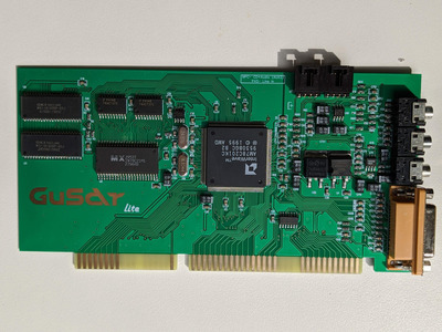
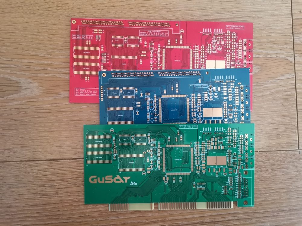
This is what the card should look like (from chipkin.ru):
And this is what my card looks like:
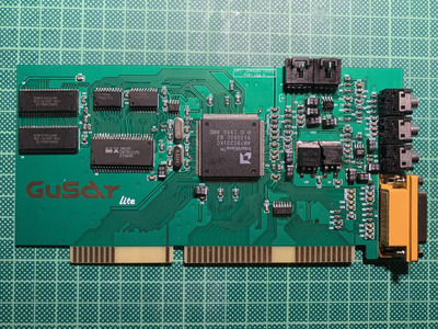
And the traces above the latches have a bit of their conformal coating removed, that is true. The PCB's quality is not as high as I am used from e.g. JLCPCB. The Renovation card for example is of better quality I noticed. I think the scratches probably happened somwhere in the shipping. However the coating is easily damaged as well, e.g. I have 1 or 2 more spots where I damaged the coating while reflowing with the iron, by simply wiping across it without much pressure. EDIT: I tested two traces that I could follow visually and they seem to have continuity.
I was using EO-FP-002 synthetic rosin flux (https://emilotto.de/produkt/eo-fp-002-2/?lang=en). Not sure if it is conductive? I cleaned the card pretty well with lots of IPA, but there are some remains between some of the polarized caps and maybe beneath the ICs.
I think I will stay off SMD projects for a while... At least until I get one with a stencil and I have a hot air station. I fear I have damaged this one beyond my capabilities to repair! 😒
Reply 2368 of 3172, by keropi

Rank
l33t++
- Rank
- l33t++
^ don't give up smd, you just need to familiarize with it... get a TS-100 soldering iron with a BC-2 tip and it will help you much with smd soldering. (or a similar tip for your soldering iron)
With a little practice you'll do just fine you don't necessarily need hot air or ovens if you only do a couple of cards for personal use.
Reply 2369 of 3172, by root42
Rank
l33t
- Rank
- l33t
Yes, I am using a BC2, and I was pretty proud at how the card turned out, visually. I am using a KSGER T12 soldering station, which uses Hakko compatible tips. Plus high quality flux, which helped a lot in soldering the tiny legs. So I think I am pretty well equipped. But some parts, like the black caps, can't be easily soldered with an iron, since they are spaced too close together. I reflowed those with a hot air station at a friend's place.
Also I think doing the ICs is also much easier with stencil and hot air. But yeah, as a kit with only one board this doesn't make sense. But honestly: I don't know what's wrong with the card.
Reply 2370 of 3172, by TechieDude
Rank
Member
Maybe hot tweezers could help you with those parts. Does anyone here use these?
Reply 2371 of 3172, by root42
Reply 2372 of 3172, by MJay99
Rank
Member
root42 wrote on 2020-06-10, 22:04:I think I will stay off SMD projects for a while... At least until I get one with a stencil and I have a hot air station. I fear I have damaged this one beyond my capabilities to repair! 😒
I'll hopefully be receiving and doing one soon, too (with hot air station and stencil). Gonna report the outcome to you, then. If it works, maybe I could even have a closer look at your card also.
Reply 2373 of 3172, by 640K!enough
Rank
Oldbie
It's difficult to tell from the pictures posted so far, but I think you may still have a few solder bridges on the InterWave. At the very least, have a close look at the side of the chip nearest the ISA connector under bright light, and with magnification, if available. If you can take some well-lit macro shots of each side of the chip; that might help too.
I compared the two board shots you posted, and the orientation of the capacitors seems to match.
Reply 2374 of 3172, by root42
Rank
l33t
- Rank
- l33t
Here is a closeup video of most of the ICs:
Reply 2375 of 3172, by 640K!enough
Rank
Oldbie
That was a little difficult for me to follow. Trying to match the video with your pictures to gain some sort of orientation on the card, I still think there is a bridge on the InterWave, on the side closest to the ISA connector, near C723 and above C4. There may be others, but it's difficult to tell.
Reply 2376 of 3172, by MJay99
Rank
Member
root42 wrote on 2020-06-11, 06:53:Here is a closeup video of most of the ICs:
@1:13 in your video I can see this:
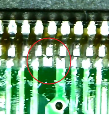
Maybe worth having a look at it?
Reply 2377 of 3172, by Synoptic
Reply 2378 of 3172, by 640K!enough
Rank
Oldbie
MJay99 wrote on 2020-06-11, 11:57:@1:13 in your video I can see this:
gusar.jpg
That's one of the questionable spots I was trying to point out. There is a similar one at 1:39, I think. They could just be solder "whiskers" that don't actually make contact with anything else, but it would be a good idea to take a look.
Reply 2379 of 3172, by shock__

Rank
Oldbie
- Rank
- Oldbie
kompas-rus wrote on 2020-06-09, 15:13:shock__ wrote on 2020-05-19, 16:56:Alternative is so simply break off the excess on the Vibra brackets, as I did 😉
Hi, as promised, I will give you 3 boards as a gift, write to me.
http://chipkin.ru/wp-content/uploads/2020/06/ … 218-rotated.jpg
Will do 😉 Seems like we briefly missed a chance, as I ordered 2 Pentagon 1024SL 2.2 boards from you 😉
I'll write you to your usual e-mail ... or do you prefer a PM on here?
Current Project: new GUS PnP compatible soundcard
[Z?]