VOGONS


Reply 1220 of 3172, by 640K!enough

User metadata
Rank Oldbie
Rank
Oldbie

For the curious, there has been some progress. Since collecting the list of instruments for Doom 2, I have sent a few ROM files to shock__, and the earlier versions didn't exactly produce satisfactory results. I suspect that we either have an early version of the ROMMAKER, or they massaged their data enough during development of the production ROM that the problems weren't apparent. The handling of the instrument parameters is rather strange at times, and their method of converting 16-bit instrument samples to 8-bit was rather crude.

The result was clipping and a certain amount of distortion and background hiss. I have changed that for a slightly better conversion method, and made other refinements. I just sent shock__ another test ROM, and we'll know if that produced any improvement as soon as he is able to test.

With a little more testing and refinement, I think the ROMMAKER will be ready, and we will be able to move on other tasks.
Reply 1221 of 3172, by elianda

User metadata
Rank l33t
Rank
l33t

Is it possible to generate a custom ROM that works with Megaem ?
I am asking because a lot games require UltraMID API and Megaem provides it with a very low memory footprint of 768 bytes.

Retronn.de - Vintage Hardware Gallery, Drivers, Guides, Videos. Now with file search
Youtube Channel
FTP Server - Driver Archive and more
DVI2PCIe alignment and 2D image quality measurement tool

Reply 1222 of 3172, by 640K!enough

User metadata
Rank Oldbie
Rank
Oldbie
elianda wrote:

Is it possible to generate a custom ROM that works with Megaem ?

From shock__'s previous comments, it seems that it can be made to work, however it seems to be quite sensitive to the content of the particular ROM. Figuring out exactly what is required for it to work may be rather tedious, as the only way to do any of this testing for now is for me to generate a new ROM and send it to shock__, who then has to remove the IC from the board, program it and re-install it for testing. It is doable, but it will be tedious.

Reply 1223 of 3172, by 640K!enough

User metadata
Rank Oldbie
Rank
Oldbie

Time for another progress report. With the recent changes to the ROMMaker, things seem to have improved somewhat, but I'm not quite satisfied just yet. The most recent recording provided by shock__ can be found here. Any comments or feedback would be appreciated. All instrument samples were converted to 8-bit, and there was still barely enough room in the 1 MiB ROM.

There is still the matter of the slight noise/click that seems to follow the kick drum in STRIVING.MID, which I haven't been able to isolate yet. The fact that the bass and a few other instruments wouldn't fit helps make the problem easier to hear, however. It also seemed to be present in the earlier recording of MELLOW55.MID, which was produced with a ROM containing 16-bit instrument samples.

The MIDI files from Doom 2 start around 8:30. That is playback of the files that I posted a little while ago, under Windows. There is the strangeness of the echo that seems limited to the percussion channel, and only under Windows. It was not present, that I could tell, in the playback of the other files, nor does it exist in output from real Doom 2 using IWSBOS. None of my non-UltraSound cards produce that strangeness, either.

Reply 1224 of 3172, by Batyra

User metadata
Rank Member
Rank
Member

Guitar from about 12:30 (doom track map1) souds nice!
That percussion echo is annoying indeed.

I have some doubts about percussion on begginig of doom intro... something is wrong with it like wrong tunes. On some of my daughterboards it sound similar.

Visit my website: http://www.collection.batyra.pl

Reply 1225 of 3172, by 640K!enough

User metadata
Rank Oldbie
Rank
Oldbie
Batyra wrote:

I have some doubts about percussion on begginig of doom intro... something is wrong with it like wrong tunes. On some of my daughterboards it sound similar.

Thanks for your feedback. More ears would be welcome.

Those are files I found and downloaded long ago. There is a note in the file that says that it's preliminary, but my cards all sound roughly like they do in the game, so it's a bit of an odd problem. I'll wait until shock__ has a few minutes to test with the RAM bank that I sent him (same instruments, but as a RAM-loadable .FFF/.DAT bank, with 16-bit samples) before I start worrying too much. Maybe the files don't contain exactly the same music as in the game. On the other hand, if he tells me that it sounds fine with the RAM bank, then I have more work to do.

Reply 1226 of 3172, by Atomizer_Zero

User metadata
Rank Newbie
Rank
Newbie

That drum echoing sounds like a sustain effect has been applied but the drum sound can't be sustained so it causes it to echo. I noticed a slight lack of sustain in the first song too.

Reply 1227 of 3172, by 640K!enough

User metadata
Rank Oldbie
Rank
Oldbie

That's an interesting idea, what led you to that theory? I'm not even sure the percussion has loop points defined or sustain enabled. That is something I will have to look into in greater detail. I am working on other related software for now, and will share the details of that effort shortly. I will get back to this issue soon.

Reply 1228 of 3172, by shock__

User metadata
Rank Oldbie
Rank
Oldbie

Some smaller news ... a friend of mine has found a cheap source for suitable, unused 16MB SIMMs. Just confirmed they're good to go on my prototype - 32x4MB organization, 60ns.
Price per piece would be 2€

Anyone interested?

EDIT: Meh ... turns out they're already out of stock.

Current Project: new GUS PnP compatible soundcard

[Z?]

Reply 1229 of 3172, by 640K!enough

User metadata
Rank Oldbie
Rank
Oldbie

I've been mostly silent, but not idle. Fuguring that it would be wasteful to expect everyone who wants to build such a card to have a flash programmer, I started looking for alternatives. As a first step, I wanted to make sure I could produce a design that would allow software to write to the chip. To that end, I started prototyping a parallel port programmer that I intend to have support a very limited number of chips (or maybe even just one type of flash). This will either serve as a learning phase for later implementation of in-circuit programming on the ARGUS board itself, or as the eventual end product. The advantage is that one should be able to assemble one of them for less than $10 in parts (plus a simple PCB, if we go that route).

Since I couldn't source the part that shock__ is using quickly or cheaply, I decided to start with a part that has a slightly simpler programming protocol. It is a 3.3V part, and I am using similar chips to those already on the board to provide level translation "for free". If we like this approach for programming the chips, I will worry about getting a few of the AMD chips and making the necessary adjustments.

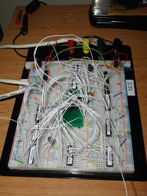
It's still a fairly early-stage prototype, but my current "rats' nest" is pictured below:

Prototype.jpg
Filename
Prototype.jpg
File size
439.18 KiB
Views
1314 views
File license
Fair use/fair dealing exception

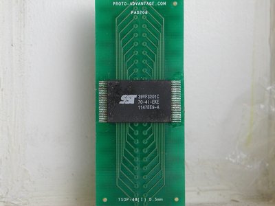
This is the current flash chip, on its adapter board:

Flash.jpg
Filename
Flash.jpg
File size
222.21 KiB
Views
1314 views
File license
Fair use/fair dealing exception

I am currently still dealing with a few design revisions and timing gremlins, but the basic design should be workable. If anyone has any better ideas, please do share.

Reply 1231 of 3172, by gdjacobs

User metadata
Rank l33t++
Rank
l33t++
640K!enough wrote:

It's still a fairly early-stage prototype, but my current "rats' nest" is pictured below:

Prototype.jpg

Looks ready for production! Just need a 200 layer PCB. 😎

All hail the Great Capacitor Brand Finder

Reply 1232 of 3172, by 640K!enough

User metadata
Rank Oldbie
Rank
Oldbie
gdjacobs wrote:

Looks ready for production! Just need a 200 layer PCB. 😎

A 200-layer board, you say? It looks that bad, does it? This little endeavour reminded me why these solderless monstrosities were never my favourite tools. I have already spent more hours than I care to count hunting down inconsistent or outright incorrect behaviour, caused by loose, intermittent or pulled connections. I should have at least wire-wrapped the thing from the start; it might have avoided a good deal of unnecessary frustration.

While there are still a few timing issues and one mystery failure condition to deal with, data transfer testing, reading and resetting the chip seem to work fairly consistently. I haven't tested my write implementation yet. If I don't have to slow it down to avoid corruption, transfer speeds are quite passable; nowhere near the performance of a commercial programmer, but it shouldn't take an eternity, either.

For some reason, every few thousand data transfers, one of the latches will become enabled without my having selected it and take on a new, incorrect value. This results in the flash coming out of suspend, and dumping data on the "bus" when it shouldn't, corrupting the data being transferred. My theory, so far, is that it's due to the voltage thresholds being a little different for some of the parts, and an additional select signal is being generated while the inputs are not yet valid. I already have a few ideas that I think may solve the problem, but feel free to chime in if you have any input.

Reply 1233 of 3172, by gdjacobs

User metadata
Rank l33t++
Rank
l33t++
640K!enough wrote:

A 200-layer board, you say? It looks that bad, does it?

Well, there was a bit of hyperbole on my part. Breadboarding is always messy.

All hail the Great Capacitor Brand Finder

Reply 1235 of 3172, by 640K!enough

User metadata
Rank Oldbie
Rank
Oldbie
gdjacobs wrote:

Well, there was a bit of hyperbole on my part. Breadboarding is always messy.

I know, I took it as a clever, but truthful stab at my mess. Just for good measure, I've made it into an even bigger mess since that picture was taken.

Synoptic wrote:

sometimes, parts from a different manufacturer will solve such behaviours.

I think I have that problem fixed. It looks like my theory was at least partly right. I added another 5V-tolerant latch between the logic that generates the select signals and the parallel port, and that seems to have made enough of a difference in the voltage thresholds and rise/fall times that the problem hasn't shown itself since. I still want to do a little more testing to be sure, but it looks like that has eliminated the latch selection problems, and resulting corruption, without having to introduce additional delays via the software.

Reply 1236 of 3172, by gdjacobs

User metadata
Rank l33t++
Rank
l33t++
640K!enough wrote:

I know, I took it as a clever, but truthful stab at my mess. Just for good measure, I've made it into an even bigger mess since that picture was taken.

Well, I'm happy I got that right. Anyway, it's head and shoulders more clean than that weird tablet prototype Dave Jones reviewed a while back.

All hail the Great Capacitor Brand Finder

Reply 1237 of 3172, by matze79

User metadata
Rank l33t
Rank
l33t

Seems i found right PS/2 socket,
72 PIN RIGHT ANGLE 45DEG SIMM SOCKET £4 61 In Stock [0072]
would this fit ?

https://www.exxoshost.co.uk/atari/last/storenew/

maybe this helps 😀

https://www.retrokits.de - blog, retro projects, hdd clicker, diy soundcards etc
https://www.retroianer.de - german retro computer board

Reply 1239 of 3172, by 640K!enough

User metadata
Rank Oldbie
Rank
Oldbie

After spending hours searching for the source of additional strange behaviour on my rats'-nest prototype, only to find one connection mistake and numerous loose connections, I decided, in frustration, to start designing a board for the purpose. With the schematic complete in EAGLE, I was rudely reminded that I never did upgrade to a paid version, and had only the default postage-stamp-sized board space to work with. Needless to say, I can barely even fit all of those DIP parts, regulators and a 48-pin DIP socket (for the TSOP adapter) onto a board of that size, much less route all of the traces.

Now that Autodesk got their mitts on EAGLE and seems bent on forcing the subscription model on all users, I have completely lost interest. The way their site works now, I can't even find the answer to one critical question: how much? So, as it stands now, I am doing the schematic over in KiCad. With any luck, I might get to the layout, etching a board and completing the software somewhat soon. Then we can get back to figuring out what we will do with the ROMs.

Still haven't managed to find an InterWave board at anything resembling a sane price, though.