VOGONS


HardMPU, anyone?

Topic actions

Reply 20 of 608, by Jepael
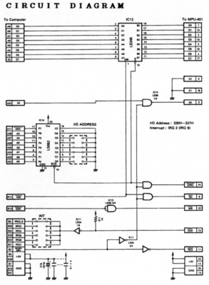
User metadata
Rank Oldbie
Rank
Oldbie
ab0tj wrote:

This: http://www.nomad.ee/micros/isapic.gif looks almost ideal, but I'm still wrapping my head around the logic.

In general that is a good circuit to start. Just ask if you have a specific question.

Yes, you need data in latch, data out latch and some control flip-flops. Never put the microcontroller sitting directly on the ISA bus. Well unless it has a suitable interface for doing that, like PC keyboard controllers do.

The point is when PC writes to IO port, the data gets written to a latch, and the write signal sets a flip-flop as a flag that data is written. Then this flag is available for PIC and PC status IO port, so that PC knows it is not free to write next byte, and PIC knows it must now read the latched data, and to reset the write flip-flop.

Also same thing to other direction. When PIC has data to PC, PIC writes this into a latch, and this latch signal also toggles a status flip-flop. This status flip-flop is readable by PC status IO port so that PC knows there is data for reading, and also the PIC knows the PC has not yet read it. Also, the flip-flop can raise the PC IRQ line. Then when PC reads the data port, it gets the data from latches, and the read strobe clears the flip-flop, so that again PC status says no more data, PIC knows it can write more data, and also it clears the pending IRQ.

Of course there must be the control write port as well, to reset the MCU into different modes somehow.

But I still suggest to consider the use of PIC. The original 6801 MCU is clocked at 4 MHz, running internally at 1 MHz, but it has more registers than PICs I know so comparing those clock by clock the PIC has to execute more opcodes to do the same thing as 6801. Of course you can clock PICs higher, and there are more sophisticated PICs. But still, consider something modern with free developement tools for writing large C code and good debugging capabilities. I may be biased as I havent used PICs lately, as I have used AVRs and ARMs since.

Reply 21 of 608, by alexanrs

User metadata
Rank l33t
Rank
l33t

Ooookay, guess I didn't fully understand the logic as well. Thanks Jepael, now I get how it works. Yup, that design seems good.

Now that its morning and I understood that circuit I can try to offer better feedback. First, that design doesn't really do anything when you write something on the control ports. I've read on the net this would consist of a buggy MPU-401 UART implementation, as even in UART mode it should recognize at least the reset command and return the ACK on the data port.

That being said, I think you should have an AND port after the ~CW and ~DW lines, so either of them would signal an incoming byte and activate the latch, therefore allowing data to be read. Then get a line directly from the ~DW and connect to a free GPIO on the PIC. If there is incoming data and ~DW is high, it is a command byte, if it is asserted low, it is a data byte. After reading a little it seems you do not really need cyclic buffers as I originally thought, as you should process incoming data immediately and signal when you are done on the status port. You might still want to have a little buffer containing responses from the commands (ACKs are a single byte, but I'm not sure that holds true for every command... if it does then all you need is a single byte and a flag), and have the data read procedure prioritize that buffer instead of data in the UART's RX built in buffer.

Reply 22 of 608, by Jepael

User metadata
Rank Oldbie
Rank
Oldbie

I still think you can't make PIC see PC write strobes, you have to have similar handshake with flipflops and data latches on both data and control port. This is much easier, and this is how it is done originally, to get a microcontroller executing software at 1 MHz to communicate with ISA bus with about 0.8 microsecond bus cycles. The MPU401 has some kind of "custom LSI hand-shake controller" in place of discrete flipflops and latches.

All data transfer between PC and microcontroller happen through latches, one byte at a time. The MPU401 later version MCU firmwares have enough SRAM to buffer 1700 bytes in dumb uart mode.

Reply 23 of 608, by ab0tj

User metadata
Rank Member
Rank
Member

I'm starting to see why designers of clone cards went with a GAL instead of a bunch of 74xx logic. Which I am not opposed to doing, I just have no experience with them. My EEPROM programmer can program GALs, at least.

I have been going the PIC route because I have the tools to program them, and have worked with them before. They do have free C development tools these days, too. And running off the internal oscillator, I can run it up to 32 MHZ which would be 4x the bus speed. I also am not opposed to using something else if it fits the application better, but I may not have the tools on hand to program it. It's unfortunate that the PIC PSP that is available on the 40 pin models can only work as one port, that would make things much easier on the bus interface side of things.

So, from what I'm gathering, I need the following for glue logic:

- 4 latches, one for each direction on each port
- Flip-flops for each latch to signal that it has a byte waiting
- Address decoding logic

Since I have lots of GPIO available on the PIC (25 pins on the one I was looking at) I can save some logic on the PIC side of things. Here's what I'm thinking:

- 8 for the data lines
- One output for each latch to read from/write to it
- One input from each latch to see its status (which also trigger an interrupt in the PIC)
- One output for the IRQ
- One input for the reset line.

The PIC (18F2620) has almost 4k of RAM, so a generous buffer for UART mode should not be a problem. I was also toying with the idea of adding a few commands that weren't present on the original MPU, to do things like enable and disable SysEx delay for the MT-32 Rev0.

Am I missing anything that you guys can think of? I think I'm almost to the point where I can draw up a schematic.

Reply 24 of 608, by alexanrs

User metadata
Rank l33t
Rank
l33t
Jepael wrote:

I still think you can't make PIC see PC write strobes, you have to have similar handshake with flipflops and data latches on both data and control port. This is much easier, and this is how it is done originally, to get a microcontroller executing software at 1 MHz to communicate with ISA bus with about 0.8 microsecond bus cycles. The MPU401 has some kind of "custom LSI hand-shake controller" in place of discrete flipflops and latches.

All data transfer between PC and microcontroller happen through latches, one byte at a time. The MPU401 later version MCU firmwares have enough SRAM to buffer 1700 bytes in dumb uart mode.

Wouldn't the PIC be able to see a write strobe if you hook it to the external interrupt pin? Of course, you might need a beefier PIC to be able to keep up with it, but microcontrollers are much cheaper nowadays, and I see little reason to prototype this with anything less than, say, a PIC which can run at 32MHz or 40MHz, and should be able to react fast enough (using an interrupt to be sure it won't miss the data because it is stuck somewhere else processing a command). The PIC would need to be much more powerful than the original MPU-401 anyway to implement delaying SyxEx messages to avoid overflowing old MT32's buffers anyway.

Yeah, I was hasty to say a buffer wouldn't be needed, specially for delaying SysEx delays. I just assumed the hardware FIFO buffers in the UART hardware would be able to keep up in dumb UART mode.

ab0tj wrote:
So, from what I'm gathering, I need the following for glue logic: […]
Show full quote

So, from what I'm gathering, I need the following for glue logic:

- 4 latches, one for each direction on each port
- Flip-flops for each latch to signal that it has a byte waiting
- Address decoding logic

Since I have lots of GPIO available on the PIC (25 pins on the one I was looking at) I can save some logic on the PIC side of things. Here's what I'm thinking:

- 8 for the data lines
- One output for each latch to read from/write to it
- One input from each latch to see its status (which also trigger an interrupt in the PIC)
- One output for the IRQ
- One input for the reset line.

The PIC (18F2620) has almost 4k of RAM, so a generous buffer for UART mode should not be a problem. I was also toying with the idea of adding a few commands that weren't present on the original MPU, to do things like enable and disable SysEx delay for the MT-32 Rev0.

Am I missing anything that you guys can think of? I think I'm almost to the point where I can draw up a schematic.

I don't remember how to properly use the IRQ lines. Maybe you'll need a flip flop for that as well, and avoid connecting it directly to the bus. I also don't remember how long you have to assert it low, or if there is any signal from the PC to tell you to stop doing it.

Reply 25 of 608, by ab0tj

User metadata
Rank Member
Rank
Member
alexanrs wrote:

I don't remember how to properly use the IRQ lines. Maybe you'll need a flip flop for that as well, and avoid connecting it directly to the bus. I also don't remember how long you have to assert it low, or if there is any signal from the PC to tell you to stop doing it.

The MIF-IPC-A uses an inverter to avoid directly connecting IRQ to the bus. If I am reading the MPU programming notes correctly, the IRQ would be asserted by the PIC until the PC has read all the data that the PIC had buffered for it. It would also assert IRQ when it wants more data from the PC in intelligent mode.

Reply 26 of 608, by Jepael

User metadata
Rank Oldbie
Rank
Oldbie

I have some more suggestions. They may be helpful or just plain wrong.

You need 3 latches, ISA data write, ISA data read, and ISA command write. ISA status read is not latched, it is directly the state of the "data available for reading" and "busy handling written data" signals that are in flip-flops. You do need to buffer them though so you can enable a buffer driving these flipflop signals to ISA bus.

You don't need separate IRQ output to ISA. There is already the flip-flop holding a status that MPU data is awaiting to be read, and reading the data will clear the flip-flop and thus the pending interrupt. (Yes you might need inverting the signal or something though, but it's the same signal, isn't it? Just look at the signal chart between MPU ISA card and MPU metal box).

Input for ISA RESET line? It should be best to connect really to PIC reset, not GPIO. You really want the PIC to reset when your PC does, at least when developing PIC code and it hangs. But it may also need to clear the flip-flops to a state that both ISA and PIC think that there is no data for them and everything is ready, or the PIC could also clear these signals if possible.

Also, do the latch strobe signals really need to generate an interrupt in the PIC? It is a nice add on though. I was just thinking the PIC could sit in a tight main loop and poll stuff from ISA, as the ISA bus won't have any overruns. The MIDI uart on the other hand can't be polled unless you guarantee you poll it at over 3125 Hz rate as that is the max rate you get bytes on the wire. But this is something I just wanted to ask, I am not saying whether it should or should not use PIC interrupts.

Reply 27 of 608, by ab0tj

User metadata
Rank Member
Rank
Member
Jepael wrote:

I have some more suggestions. They may be helpful or just plain wrong.

You need 3 latches, ISA data write, ISA data read, and ISA command write. ISA status read is not latched, it is directly the state of the "data available for reading" and "busy handling written data" signals that are in flip-flops. You do need to buffer them though so you can enable a buffer driving these flipflop signals to ISA bus.

You don't need separate IRQ output to ISA. There is already the flip-flop holding a status that MPU data is awaiting to be read, and reading the data will clear the flip-flop and thus the pending interrupt. (Yes you might need inverting the signal or something though, but it's the same signal, isn't it? Just look at the signal chart between MPU ISA card and MPU metal box).

Ah, so the status port only shows the status of waiting bytes? I was under the impression it was used for other information as well, but admittedly I hadn't looked too closely at that part yet. But, doesn't IRQ need to have the possibility of being set for other things during intelligent mode operation?

Jepael wrote:

Input for ISA RESET line? It should be best to connect really to PIC reset, not GPIO. You really want the PIC to reset when your PC does, at least when developing PIC code and it hangs. But it may also need to clear the flip-flops to a state that both ISA and PIC think that there is no data for them and everything is ready, or the PIC could also clear these signals if possible.

That is a good point. There is really no reason I can think of where the PIC couldn't go through a hard reset at the same time as the PC. And it would probably need to manually clear the flip-flops. Reading the ports at startup by the PIC would clear the flip-flops on its side, but the PC may still think there is data waiting or the IRQ may still be set.

The MPU reset command, however, should probably only be a software function so things like the state of SysEx delay can be remembered.

Jepael wrote:

Also, do the latch strobe signals really need to generate an interrupt in the PIC? It is a nice add on though. I was just thinking the PIC could sit in a tight main loop and poll stuff from ISA, as the ISA bus won't have any overruns. The MIDI uart on the other hand can't be polled unless you guarantee you poll it at over 3125 Hz rate as that is the max rate you get bytes on the wire. But this is something I just wanted to ask, I am not saying whether it should or should not use PIC interrupts.

Also a good point. Polling the state of the flip-flops would probably work just as well, and probably simplify the software end of things. Thankfully, whether or not a PIC interrupt occurs can be controlled in the firmware. It can be set either way depending on how firmware development goes.

Reply 28 of 608, by alexanrs

User metadata
Rank l33t
Rank
l33t

Using interrupts would probably be a safer approach initially, as you can keep the ISRs lean (by making it just push stuff in or out of the buffers), and therefore not risk missing a byte in case the software isn't optimized yet. It may also make the card a lot more resilient to a heavily OCed ISA bus. If the main loop is tight enough, though, it is probably not necessary.

Reply 29 of 608, by ab0tj

User metadata
Rank Member
Rank
Member
alexanrs wrote:

Wouldn't the PIC be able to see a write strobe if you hook it to the external interrupt pin? Of course, you might need a beefier PIC to be able to keep up with it, but microcontrollers are much cheaper nowadays, and I see little reason to prototype this with anything less than, say, a PIC which can run at 32MHz or 40MHz, and should be able to react fast enough (using an interrupt to be sure it won't miss the data because it is stuck somewhere else processing a command). The PIC would need to be much more powerful than the original MPU-401 anyway to implement delaying SyxEx messages to avoid overflowing old MT32's buffers anyway.

Are you saying in this case, have the read and write strobe cause interrupts in the PIC so that the PIC can directly read and write data to the bus (through a buffer, of course), instead of using latches? That was my thinking on how to do this in the first place, but I'm not sure if the PIC would have time to, say, switch it's data port to an input and capture the data before the bus cycle ends. Though, I see an 8-bit transfer has 4 wait states by default, so it may be a non-issue.

Reply 30 of 608, by alexanrs

User metadata
Rank l33t
Rank
l33t

You can keep the latches and still use the interrupts - though that might be a bit redundant. Or you can just go trigger happy with your GPIO ports and use 16 pins (8 for output, 8 for input) if you have enough. I don't think it would take the PIC that long to switch the port to output/input and read it, though. Probably just two cycles, then you'd be free to take as long as you want to. I personally like interrupts for some reason.
I find it weird that you would have 25 GPIO ports, though, isn't it 24? Aren't they supposed to be in groups of 8 (so you can read an entire byte on a single instruction)?

Reply 31 of 608, by ab0tj

User metadata
Rank Member
Rank
Member
alexanrs wrote:

You can keep the latches and still use the interrupts - though that might be a bit redundant. Or you can just go trigger happy with your GPIO ports and use 16 pins (8 for output, 8 for input) if you have enough. I don't think it would take the PIC that long to switch the port to output/input and read it, though. Probably just two cycles, then you'd be free to take as long as you want to. I personally like interrupts for some reason.
I find it weird that you would have 25 GPIO ports, though, isn't it 24? Aren't they supposed to be in groups of 8 (so you can read an entire byte on a single instruction)?

There are 3x 8-bit ports, and it looks like you can also use the MCLR pin as a GPIO. If course, many of those pins are also shared with other functions such as the UART TX and RX, which will be needed for MIDI data.

I think I will "breadboard up" the MIF-IPC based design and see if keeping the ISR as short as possible (as mentioned, just push data into/out of buffers) is good enough to keep up with the bus. Seems to me, it wouldn't use up any more of the PIC's time to do it this way. I can just by default leave the status bits as output to be polled by the PC, and switch to other functions as needed, as long as those transitions happen in time to keep up with bus timings.

Looking forward to seeing how this works out. It may become redundant after keropi's clone is released, but still a fun project.

Reply 32 of 608, by alexanrs

User metadata
Rank l33t
Rank
l33t

Nah, I wouldn't call it redundant, and delayed SysEx messages would make it an interesting alternative. The more the merrier =)
And yeah, one can always switch from using interrupts to polling just with a firmware update, so you can just try stuff out and see what works best.

Reply 33 of 608, by ab0tj

User metadata
Rank Member
Rank
Member

By the way, here is the schematic of the MIF-IPC-A. Basically I'm thinking, with this design, hook all the signals on the right to the PIC.

Attachments

  • Capture.PNG
    Filename
    Capture.PNG
    File size
    529.22 KiB
    Views
    2193 views
    File license
    Fair use/fair dealing exception

Reply 34 of 608, by ab0tj

User metadata
Rank Member
Rank
Member

Another crazy idea, just throwing it out there. If the processing requirements become too much for a PIC to handle, what do you guys think of splitting the functions into two PIC chips: One to handle I/O (and therefore can do UART mode by itself), and one to do intelligent mode functions? The two can communicate via a fast protocol like I2C to exchange information, and the I/O PIC can buffer messages while the intelligent PIC is busy doing other things.

Reply 35 of 608, by alexanrs

User metadata
Rank l33t
Rank
l33t

Since the PIC has the UART in hardware I don't believe you'll gain that much by splitting things. Also, its not like the original MPU-401 was very powerful to begin with. Getting a beefier PIC (or maybe OCing one if that doesn't make the UART hardware throw a fit) would probably give better results.

Reply 36 of 608, by ab0tj

User metadata
Rank Member
Rank
Member
alexanrs wrote:

Since the PIC has the UART in hardware I don't believe you'll gain that much by splitting things. Also, its not like the original MPU-401 was very powerful to begin with. Getting a beefier PIC (or maybe OCing one if that doesn't make the UART hardware throw a fit) would probably give better results.

True. Hopefully running at 32 (or 40 if I use a crystal) is good enough. I suppose falling back to latches is probably cheaper than a second PIC anyway.

Reply 37 of 608, by Jepael

User metadata
Rank Oldbie
Rank
Oldbie

My advice, don't split into two PICs. No overclocking either. If one can't do it, then it's time to put something other anyway.

I checked the 18F2620 datasheet, and it says the internal oscillator is typically accurate to 1%, but could be up to 2%. Also it appears that the PLL can have up to 2% jitter. Sounds like asking for trouble regarding UART communications. MIDI specs require 1% accuracy. So please use a crystal that nicely divides to MIDI baud rate, and preferably without PLL if possible, so we get better than 0.1%. This is not a place to skimp few cents and later on figure out why half of the boards work and the other half don't.

Regarding the interrupt line, it appears it stays active until all bytes are read, so it is not just blazingly fast toggling signal indicating data latch has data for ISA bus. So it is possible there is a need for the handshake signal, the "data ready for reading" status bit, and the nDSR interrupt line to be somehow separate.

Reply 38 of 608, by ab0tj

User metadata
Rank Member
Rank
Member
Jepael wrote:

My advice, don't split into two PICs. No overclocking either. If one can't do it, then it's time to put something other anyway.

I checked the 18F2620 datasheet, and it says the internal oscillator is typically accurate to 1%, but could be up to 2%. Also it appears that the PLL can have up to 2% jitter. Sounds like asking for trouble regarding UART communications. MIDI specs require 1% accuracy. So please use a crystal that nicely divides to MIDI baud rate, and preferably without PLL if possible, so we get better than 0.1%. This is not a place to skimp few cents and later on figure out why half of the boards work and the other half don't.

Regarding the interrupt line, it appears it stays active until all bytes are read, so it is not just blazingly fast toggling signal indicating data latch has data for ISA bus. So it is possible there is a need for the handshake signal, the "data ready for reading" status bit, and the nDSR interrupt line to be somehow separate.

EDIT: Ok, yes, 2% error is 2% no matter how many times you divide it. Got it. Perhaps a 32MHz external oscillator?

Reply 39 of 608, by Jepael

User metadata
Rank Oldbie
Rank
Oldbie

Perhaps. I did try to read the datasheet, but I can't really say what frequencies are possible in what modes. I believe it can take anything up to 40MHz in external oscillator mode, and up to 25 MHz quartz crystal. Anyway, the UART module should get exactly 31250 baud rate at any multiple of 500 kHz when in 16x oversampling mode so this is not a problem. It seems also 4x overasampling mode is available, but I don't recommend it. Most other microcontrollers offer 8x oversampling mode to double the baud rates compared to the default 16x oversampling mode. Interesting, there is also a 64x oversampling mode.

But yes, 32MHz external oscillator will work nicely.