Reply 160 of 608, by ab0tj
Rank
Member
Looks perfect, run it! 😁
Looks perfect, run it! 😁
Gotta stop for today, did a few footprint corrections and started a bit the part placement.
I/O, I/O,
It's off to disk I go,
With a bit and a byte
And a read and a write,
I/O, I/O
Goodluck ! 😀
What Software do you use ?
Ah ok, KiCad.
Does it contain a Auto Router ?
https://www.retrokits.de - blog, retro projects, hdd clicker, diy soundcards etc
https://www.retroianer.de - german retro computer board
Yes it does, but autorouters are for wimps. 😀
I'm about 50% through but stuff at work keeps interfering with my progress.
I/O, I/O,
It's off to disk I go,
With a bit and a byte
And a read and a write,
I/O, I/O
Any update on this project? 😀
Now for some blitting from the back buffer.
Any progress, stamasd? I ask because I will be ordering some prototype boards for another project, so I think I may whip up a board for this as well. Mine would be with the autorouter though 😜
Sorry, no progress. I got sidetracked by many things.
One word of caution about the autorouter. I tried it once, and it made a mess.
I/O, I/O,
It's off to disk I go,
With a bit and a byte
And a read and a write,
I/O, I/O
Here's a simplified and cleaned up schematic. Putting this out there in case anyone finds errors before I start laying out a board...
Awesome work!
386DX-40MHz-8MB-540MB+428MB+Speedstar64@2MB+SoundBlaster Pro+MT-32/MKII
486DX2-66Mhz-16MB-4.3GB+SpeedStar64 VLB DRAM 2MB+AWE32/SB16+SCB-55
MY BLOG RETRO PC BLOG: https://bitbyted.wordpress.com/
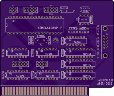
Just a teaser for you guys...
Cool beans! When can we order the PCB? 😁
I/O, I/O,
It's off to disk I go,
With a bit and a byte
And a read and a write,
I/O, I/O
Sent you a PM, I want to help moving things along.
I/O, I/O,
It's off to disk I go,
With a bit and a byte
And a read and a write,
I/O, I/O
Did you end up going with the last posted layout?
All hail the Great Capacitor Brand Finder
I did. The prototype boards I ordered should be here this week.
wrote:Did you end up going with the last posted layout?
So, I was thinking about this one... what do you think about putting a Wavetable Header on the card and wiring an (optional?) audio-out jack for use with a Wavetable card? Would that be actually useful, or am I thinking up solutions to problems that don't exist?
You're not the first to bring this up. I think it's a good idea. Someone else may have to take on that part of the project though as analog design is not really my strong suit 😎
wrote:So, I was thinking about this one... what do you think about putting a Wavetable Header on the card and wiring an (optional?) audio-out jack for use with a Wavetable card? Would that be actually useful, or am I thinking up solutions to problems that don't exist?
wrote:Someone else may have to take on that part of the project though as analog design is not really my strong suit 😎
Well, I won't claim to be an expert, but it's not that difficult. Just have a 270ohm (or maybe 220ohm, as you have some of those on the board already) resistor inline with the audio signal lines for current protection, and ideally some ground traces adjacent to the signal traces for some EMI protection. Based on some quick googling, it looks like the audio signals are on pin 20 (right) and pin 24 (left) of the wavetable header...
I approve of this 😀 Nice effort.
Always nice to see people design new hardware to replace old solutions or ease up the market.
Not sure if it's an issue with the preview or you already did that, but I'd remove all soldermask near the ISA connector, it tends to wear off over time there and can isolate pins when it has flaked off.
Also: maybe add a bit of 'via stitching' to additionally connect both ground planes (probably not required, but looks nice)?
Current Project: new GUS PnP compatible soundcard
[Z?]
wrote:Well, I won't claim to be an expert, but it's not that difficult. Just have a 270ohm (or maybe 220ohm, as you have some of those on the board already) resistor inline with the audio signal lines for current protection, and ideally some ground traces adjacent to the signal traces for some EMI protection. Based on some quick googling, it looks like the audio signals are on pin 20 (right) and pin 24 (left) of the wavetable header...
Fair enough, I'll look into adding that once I verify that this 'prototype' works.
wrote:Not sure if it's an issue with the preview or you already did that, but I'd remove all soldermask near the ISA connector, it tends to wear off over time there and can isolate pins when it has flaked off.
Also: maybe add a bit of 'via stitching' to additionally connect both ground planes (probably not required, but looks nice)?
Thanks for the kind words and suggestions. I had not done either of these with the current iteration of the design, but I will keep this in mind before I send off the gerbers to get any more boards made. Both suggestions make sense.