VOGONS


CVX4 : high quality covox adapter

Topic actions

Reply 200 of 484, by stamasd

User metadata
Rank l33t
Rank
l33t

There's a wide range of values between 7.5k and 100k. I have ordered a bunch of precision resistors and will do some testing with various values when they get here. Which may be a while.

I/O, I/O,
It's off to disk I go,
With a bit and a byte
And a read and a write,
I/O, I/O

Reply 201 of 484, by Scali

User metadata
Rank l33t
Rank
l33t

Here's my recording of Crystal Dream from my 286 at 36 kHz mixing, with the CVX-1 with 100k resistors:
https://soundcloud.com/scali/cvx-1-crystal-dream-286-20-100k
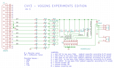
I removed the resistor which was marked as 'R10' on the PCB. If I'm not mistaken, this is the last resistor before the output, and was the one that dreamblaster pointed out for removal.
It seems to have made the output somewhat louder (although you can still hear a bit of the low hum I mentioned), and perhaps also a bit brighter.
For comparison, here's the earlier CVX-2 recording on the same machine with the same settings, with 7.5k resistors:
https://soundcloud.com/scali/286-36khz

I have to say, the difference in sound quality is marginal. There may be a slight difference in brightness, but in terms of 'noisiness' and linearity of response, they seem to be very similar. The 100k resistors just make the output a lot softer, causing more problems with preamplification (both the hum, and you also hear more electrical noise from the PSU/HDD/etc coming through the output now).

One thing that particularly strikes me is how the fade-outs aren't really fading out. It seems the D/A conversion has a very non-linear dynamic range, so the low values are nearly as loud as the high values, causing things like quantization noise to be very apparent in softer areas. It sounds very compressed (a compressor in the analog audio sense that is).
Sadly it's difficult to judge against the real Covox, because MobyGamer's recordings were done on a much faster machine, and the fade-out seems to be dependent on CPU-speed. Still, I seem to pick up quite a bit of quantization noise at the end of the quick fadeouts in his recordings.

http://scalibq.wordpress.com/just-keeping-it- … ro-programming/

Reply 202 of 484, by MobyGamer

User metadata
Rank Member
Rank
Member
MobyGamer wrote:

I could shunt the same resistor on the CVX-1 and make recordings, but since it also uses 7.5k/15k resistors, I don't think it will sound any better.

Wait, I'm wrong -- I just looked at the CVX-1 Serge sent me and it uses 100k resistors. I'll make the same test recordings and post them shortly.

Reply 203 of 484, by dreamblaster

User metadata
Rank Oldbie
Rank
Oldbie

the CVX-3 'VOGON EXPERIMENTS EDITION' PCB's arrived 😀
this will allow easier experiments with different values / combinations (using jumpers).

CVX3.png
Filename
CVX3.png
File size
26.73 KiB
Views
1085 views
File license
Fair use/fair dealing exception
CVX3_photo1.jpg
Filename
CVX3_photo1.jpg
File size
358.88 KiB
Views
1085 views
File license
Fair use/fair dealing exception
CVX3_photo2.jpg
Filename
CVX3_photo2.jpg
File size
108.55 KiB
Views
1085 views
File license
Fair use/fair dealing exception

Visit http://www.serdashop.com for retro sound cards, video converters, ...
DreamBlaster X2, S2, S2P, HDD Clicker, ... many projects !
New X2GS SE & X16GS sound card : https://www.serdashop.com/X2GS-SE ,
Thanks for your support !

Reply 204 of 484, by MobyGamer

User metadata
Rank Member
Rank
Member

Okay, CVX-1 using 100k resistors, no shunting or filtering:

ftp://ftp.oldskool.org/pub/misc/temp/LPTDAC_c … al%20dream.flac
ftp://ftp.oldskool.org/pub/misc/temp/LPTDAC_c … t%20corpus.flac

It still sounds muted/muffled compared to the original ST, and the output level was high enough that I didn't shunt R10 on it because I'm fairly sure the output level would have been too high.

The CVX-3 "Experimenter's version" scares me 😳 Has it been determined why the other designs, even with 100k resistors, don't sound as bright/clear as the original Speech Thing? If that's been determined, will the CVX-3 sound very close or identical to the original ST?

Reply 205 of 484, by dreamblaster

User metadata
Rank Oldbie
Rank
Oldbie

Hi Moby,
please try by shunting R10, it will sound brighter

Visit http://www.serdashop.com for retro sound cards, video converters, ...
DreamBlaster X2, S2, S2P, HDD Clicker, ... many projects !
New X2GS SE & X16GS sound card : https://www.serdashop.com/X2GS-SE ,
Thanks for your support !

Reply 206 of 484, by keropi

User metadata
Rank l33t++
Rank
l33t++

I like the CVX-3 design
Haven't contributed much to the thread lately - because my ears are not that good 🤣 - but I am monitoring it 😀

🎵 🎧 PCMIDI MPU , OrpheusII , Action Rewind , Megacard and 🎶GoldLib soundcard website

Reply 207 of 484, by MobyGamer

User metadata
Rank Member
Rank
Member
dreamblaster wrote:

Hi Moby,
please try by shunting R10, it will sound brighter

Okay, will do that and reply back with audio links. I'm going to use a 0-value resistor (instead of a small wire which is what I had to do with the SMC version).

Reply 208 of 484, by MobyGamer

User metadata
Rank Member
Rank
Member

Replaced CVX-1's R10 resistor with a 0 resistor (I guess this is good practice for learning to solder 😀 and made recordings:

ftp://ftp.oldskool.org/pub/misc/temp/LPTDAC_c … al%20dream.flac
ftp://ftp.oldskool.org/pub/misc/temp/LPTDAC_c … t%20corpus.flac

It sounds louder, but not particularly brighter. And none of these match the brightness/clarity of the original Speech Thing, I'm afraid. It's most apparent when you listen to them side-by-side.

However, I'm confused, because Scali's recording of Crystal Dream from his 286 at 36 kHz mixing, with the CVX-1 with 100k resistors and R10 removed, should sound identical -- but it doesn't, it sounds fairly bright (this is good). So I'm somewhat confused why that is. All I can say is that all of my recordings were made with the exact same equipment at the exact same recording levels, with pro recording hardware. Maybe the output of the CVX units were too high, and causing my recording hardware to do something strange? I don't know. Maybe someone else should try the same experiments to rule out something wrong on my end. I can ship the CVX-1 and CVX-2 to someone else if they'd like to make recordings...

Given that Covox's patents have long since expired, my vote is to just duplicate it completely, possibly based on the FTL adapter schematics.

Reply 209 of 484, by keropi

User metadata
Rank l33t++
Rank
l33t++

After all this I really feel the only way would be to examine (and maybe sacrifice) a real SP in order to replicate it. It seems there is a small detail still missing and I bet that custom resistor pack holds the answer (not that there is more to the SP anyways 🤣 🤣 🤣)

🎵 🎧 PCMIDI MPU , OrpheusII , Action Rewind , Megacard and 🎶GoldLib soundcard website

Reply 210 of 484, by matze79

User metadata
Rank l33t
Rank
l33t

Why not use a Bus Driver and a DAC IC ?

https://www.retrokits.de - blog, retro projects, hdd clicker, diy soundcards etc
https://www.retroianer.de - german retro computer board

Reply 211 of 484, by Scali

User metadata
Rank l33t
Rank
l33t
MobyGamer wrote:

Given that Covox's patents have long since expired, my vote is to just duplicate it completely, possibly based on the FTL adapter schematics.

As far as I can tell, the only difference in design between the FTL and the CVX-1 is the coupling cap on the CVX-1 that is missing on the FTL (and possibly on the real Covox as well, assuming it is not inside the resistor ladder pack).
The only difference between the CVX-1 and the CVX-2 seems to be that the CVX-1 is a 'regular' R-2R ladder, requiring you to use two types of resistors, one twice the resistance of the other (hence 2R). The CVX-2 has two resistors in series for the 2R part, so that you only need resistors of a single value to complete the R-2R ladder. You just need more of them.

http://scalibq.wordpress.com/just-keeping-it- … ro-programming/

Reply 212 of 484, by dreamblaster

User metadata
Rank Oldbie
Rank
Oldbie
Scali wrote:

As far as I can tell, the only difference in design between the FTL and the CVX-1 is the coupling cap on the CVX-1 that is missing on the FTL (and possibly on the real Covox as well, assuming it is not inside the resistor ladder pack).

Yeah, the real covox is probably just a resistor pack, without caps.
So a last attempt could be to short the coupling cap as well, on MobyGamer's CVX-1.
I made this a jumper setting on CVX-3, to allow bypassing the coupling cap.

Visit http://www.serdashop.com for retro sound cards, video converters, ...
DreamBlaster X2, S2, S2P, HDD Clicker, ... many projects !
New X2GS SE & X16GS sound card : https://www.serdashop.com/X2GS-SE ,
Thanks for your support !

Reply 213 of 484, by Scali

User metadata
Rank l33t
Rank
l33t
dreamblaster wrote:

So a last attempt could be to short the coupling cap as well, on MobyGamer's CVX-1.

Yes, I can do that on mine as well.

http://scalibq.wordpress.com/just-keeping-it- … ro-programming/

Reply 214 of 484, by MobyGamer

User metadata
Rank Member
Rank
Member
dreamblaster wrote:

Yeah, the real covox is probably just a resistor pack, without caps.
So a last attempt could be to short the coupling cap as well, on MobyGamer's CVX-1.

Okay, this is done:

ftp://ftp.oldskool.org/pub/misc/temp/LPTDAC_c … al%20dream.flac
ftp://ftp.oldskool.org/pub/misc/temp/LPTDAC_c … t%20corpus.flac

I heard no difference with the capacitor removed and replaced with a shunt. They sound identical to my ears, but my ears might be faulty.

To make sure I wasn't going crazy and there was something wrong with my recording setup, I recorded a few seconds of the test corpus, then swapped out the CVX-1 with the real Covox while the recording was still going on, then played the same few seconds. The quality difference is unmistakable. That file, unedited, is here:
ftp://ftp.oldskool.org/pub/misc/temp/LPTDAC_c … ch%20Thing.flac
(watch out for a loud POP in the middle of the file!)

I'm afraid I can't help any further, other than to send my devices to someone else (or maybe Scali, since his sounds nicer).

Reply 215 of 484, by keropi

User metadata
Rank l33t++
Rank
l33t++

^ maybe you can send one to dreamblaster to analyze that custom resistor pack - most likely the worst he'll do is desolder it and then solder it back so it won't get ruined. Just a thought 😀

🎵 🎧 PCMIDI MPU , OrpheusII , Action Rewind , Megacard and 🎶GoldLib soundcard website

Reply 216 of 484, by Jepael

User metadata
Rank Oldbie
Rank
Oldbie

I'm in the process of analyzing Jim's youtube video. Actually found it just yesterday.
It should not be too hard to determine the GND and OUT pin connections (two red wires). The R2R network for data pins is pretty straightforward, there is enough evidence that R=100K and 2R=200k.

Reply 217 of 484, by MobyGamer

User metadata
Rank Member
Rank
Member
keropi wrote:

^ maybe you can send one to dreamblaster to analyze that custom resistor pack

I meant send the CVX-1 and CVX-2 prototypes. The Speech Things stay with me 😀 now that we've confirmed the ladder uses R=100K and 2R=200k; there's no need to destroy the resistor pack.

If there is sufficient measurements and evidence to determine the ladder uses R=100K and 2R=200k, why does the 100k version of the CVX-1 sound so different, and louder? Is its ladder not constructed in the same way?

Reply 218 of 484, by shock__

User metadata
Rank Oldbie
Rank
Oldbie

Destroy?! To measure the values it even seems highly unlikely that you'd even have to unsolder the pack.
Also: Has anyone of you compared the CD output to an actual DAC? I sadly don't have one at hand and am currently not in the mood to solder one, but comparing one to the ST might make this tedious discussion irrelevant.

Current Project: new GUS PnP compatible soundcard

[Z?]

Reply 219 of 484, by MobyGamer

User metadata
Rank Member
Rank
Member

I wrote "there's no need to destroy the pack". Re-read what I wrote more carefully, perhaps? The values have already been measured. As for using an actual DAC, that would obviously produce higher-quality results and probably not cost that much (simple DAC ICs were about $3 in the 1990s, they are probably the same today), but that's up to dreamblaster as to whether he wants his project to be like that. I think he was making a project kit for beginners to solder on their own, rather than target sound quality.

I found a great article about building an LPT DAC out of resistors that had some notes on what affects the quality, how to verify if it's performing properly, etc: http://jubatian.com/articles/building-an-lpt-dac/