First post, by JimJim
Rank
Newbie
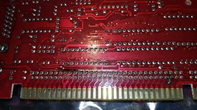
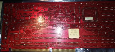
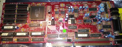
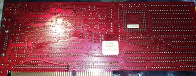
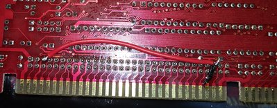
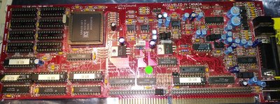
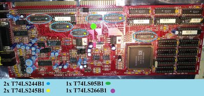
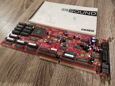
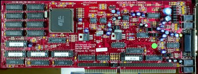
Hello, I just received a Gravis UltraSound Classic 2.4 that I purchased untested with no ram for a good price. I should receive the 8 20 pin dip 44256 drams for it in a few days. I took a glance at it when I received the card and noticed two spots where the traces looked rather dark. Sure enough, tested with my multi-meter, they were open. Both traces are connected in series to pins on the ISA card edge. So it looks like something happened in the motherboard it was in and the voltage came in one pin and straight out the other.
#1 is there a chance the chips were untouched by the extra voltage?
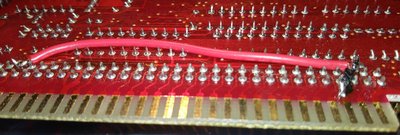
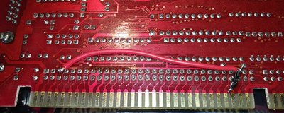
#2 Once the Traces are bridged, is there a chance I will damage a motherboard that I will test this card in?


