First post, by Kahenraz

Rank
l33t
- Rank
- l33t
I managed to snag one of these but I don't have the dongle. Does anyone know the pinout for this PCMCIA sound card?
I managed to snag one of these but I don't have the dongle. Does anyone know the pinout for this PCMCIA sound card?
I have one with the dongle, it doesn't have screws, so plastic tabs or glue, no idea how to open it...
Cables like this are heat-welded shut and can't be disassembled without destroying them. What you need is a multimeter with a beeper to help you trace which pin on the card-side connects to which pin on the output-side.
You can pickup a multimeter from any hobby store, Walmart, Home Depot, and lots of places online. Just make sure that it has a dial on it indicating that it has a buzzer. The glyph looks like a couple of waves from left to right, kind of like an antenna signal but on its side.
If you would like to own a very small but capable meter for small jobs like this, this one is my favorite:
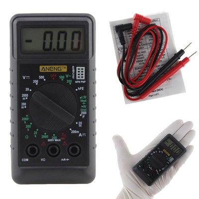
You can order it from eBay here:
https://www.ebay.com/itm/292401323840
Just be aware that it ships from Guangzhou, China and takes about a month or more to arrive. So I would recommend grabbing another one locally for this.
Signal testing is really easy. Just set the dial to the buzzer and touch the two probes together and you'll hear a beep. Then start touching input and output pins to to map out how they are connected and draw us a picture. Also be sure to identify the orientation so that I won't wire it up backwards.
If all of this outside of your comfort level, you could always mail me the dongle and I'll mail it right back. I've been on Vogons forever and I like to think there are at least a few people here that would vouch for my honesty. 😀
---
A brief history of my situation:
Funny story about the WAVjammer box. I bought it off of ebay and when I got it the box was empty! The seller hadn't even checked before listing it. I did get a refund and got to keep the box. 🤣
This week:
Sent a message to a seller of a loose WAVjammer on Amazon (it was listed by its part number rather than by name) asking if he had the dongle but he did not. Negotiated a lower price since it was incomplete and placed my order:
https://www.amazon.com/WAVjammer-16-Bit-Stere … d/dp/B00B8710QM
Now all I need to do is make a dongle. 😁
If I am successful I will consider making replicas for others as well. This might be nice for those who worry about their dongle breaking or getting lost. I for one have had many dongles fail on me over the years internally with no visible damage anywhere on the outside or to the pin headers.
I recently joined a local makerspace and am having a lot of fun doing a lot of electronic hobby stuff I've wanted to do for years!
Calling it a dongle is a not really accurate, it's more a breakout box, I don't know if there are electronic components inside or just direct connections between the 3.5" jacks and the connector to the card.
Ahh, I see. The little box may have a small amp in it, for example, and filters. Can you tell if it's just clipped shut? You might be able to get inside with a spudge tool or a guitar pick.
Even if there are components inside, you might still be able to trace which pin on the card side goes to which stereo jack with a multimeter probe. You won't know until you start poking around and see.
wrote:Ahh, I see. The little box may have a small amp in it, for example, and filters. Can you tell if it's just clipped shut? You might be able to get inside with a spudge tool or a guitar pick.
Even if there are components inside, you might still be able to trace which pin on the card side goes to which stereo jack with a multimeter probe. You won't know until you start poking around and see.
Mine is plastic welded shut. Guessing all of them are. Trying to take it apart would be very tricky to do without messing it up.
I've taken apart cordless phone battery packs that were put together like this and it can be done with an exacto knife, but is very, very hard to not slip and mess up the casing at least a little bit.
I have an analog multimeter like this one:
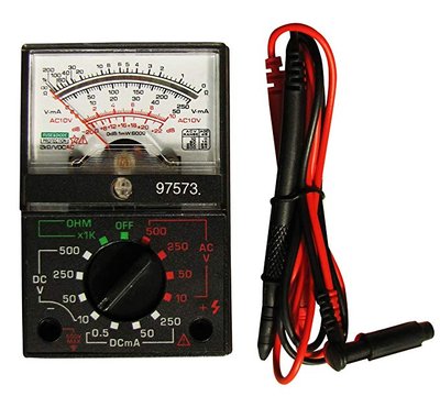
I put it on *1K Ohm function and tested the breakout box, almost all the pins on the connector to the pcmcia card gives a reading on each of the 3 contacts out of the headphone jack, drawing a picture won't help much I'm afraid...
Sounds like there's an internal amplifier, then.
All hail the Great Capacitor Brand Finder
Well that's unfortunate. Are you sure that it's glued shut and it's not able to be opened with a spudge tool?
wrote:Well that's unfortunate. Are you sure that it's glued shut and it's not able to be opened with a spudge tool?
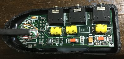
Yep, glued shut. Anyway, I managed to open mine without damaging the insides. Will have to repair the casing or make a custom case for it though. Can probably just repair it well enough to make it look like it hasn't been opened... but I would rather have a case I can open back up.
I think all the components are on the one side, but I am not about to pry the board off of the glue that is holding it to the bottom part of the case to find out for sure.

Thank you for the photos! I understand how hard it is to damage old equipment for the sake of documenting them. With the popularity of 3D printers, a replacement could easily be made.
Would you mind lifting up the cable so that I can see how many wires there are connected to the board?
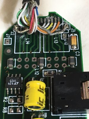
Does anyone recognize the little black chip? I'm assuming that it's an amp of some kind.
I'll try to lift up the cable, take more pics and make a diagram of what wires go where on the plug tomorrow.
I'll have to see if I can get the cover off of the board as well so we can see the traces on the underside.
Finally got a chance to take a couple more pics and figure out the wiring.
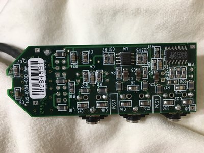
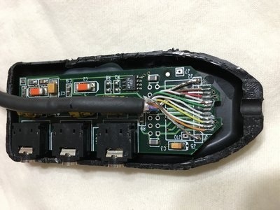
As for the wiring, it is as follows.
In the picture above, the bottom ground is 1, and the top ground is 14.
Wire colors are as follows:
1 - Ground
2 - Orange
3 - White/Orange
4 - Yellow
5 - White/Yellow
6 - White
7 - Black
8 - Green
9 - White/Brown
10 - White/Green
11 - Red
12 - White/Black
13 - Brown
14 - Ground
(To dongle pin numbers below)wire ------- 1 - 2 - 3 - 4 - 5 - 6 - 7 - 8 - 9/10 - 11 - 12 - 13 - 14dongle pin - 1 - 2 - 3 - 4 - 5 - 11 - 7 - 9 - 8/10 - 6 - 12 - 13 - 14Dongle side is like this ( O = no connection alignment pin . = connection )O . . . . O . . . O . . . . . . . O1 2 3 4 5 6 7 8 9 10 11 12 13 14
I will NOT be desoldering the IC's to trace the exact path of the traces for the through the board holes/connections under them.
Excellent. Thank you SO much! <3

