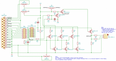
VOGONS


Reply 20 of 93, by Benedikt

User metadata
Rank Oldbie
Rank
Oldbie

I expect to see at least three more resistors – namely 10kΩ – on the back side of the SoundJr board, that, combined with the three 20kΩ resistors on the front side, extend the R-2R ladder to permit the 8 different volume levels.
But we'll see.

Reply 22 of 93, by Benedikt

User metadata
Rank Oldbie
Rank
Oldbie

No problem! Honestly, I do not expect too many surprises, at this point. The only really important thing I need to know is which of the control lines goes where.

Reply 23 of 93, by shock__

User metadata
Rank Oldbie
Rank
Oldbie

Is there a schematic for the SoundJr?
I'm currently waiting on the prototype boards for my Covox/Stereo-Covox (Stereo on 1)/FTL (no joystick part)/Disney Sound Source adapter and personally wouldn't mind adding support depending on a few factors.
Currently it's 7528 (8 bit DAC chip) powered, but wouldn't mind adding another header for discrete R2R DACs if there's interest.

Current Project: new GUS PnP compatible soundcard

[Z?]

Reply 24 of 93, by Benedikt

User metadata
Rank Oldbie
Rank
Oldbie

There is no full schematic for the SoundJr, yet, but a partial one in my second post to this thread.
The SoundJr appears to use an 11 bit 10kΩ R-2R ladder (8 data lines + 3 control lines) with an additional control line to disable the entire thing. The three most significant bits are transistor-switched and serve as volume control.

Reply 25 of 93, by Paralel

User metadata
Rank Member
Rank
Member

I took a look, and I have to say, I am really sorry. I thought I knew exactly where it was, but when I went to grab it and take the photos today, it was not indeed where I thought it was supposed to be. I must have moved it at one point and not remembered. I will have to go through my storage and locate it. I am terribly sorry about this, but I would have sincerely swore I knew exactly where it was. I am confused that it is not there. I hope it shouldn't take me long to locate it.

Reply 28 of 93, by Benedikt

User metadata
Rank Oldbie
Rank
Oldbie

Thank you, Cloudschatze! That back side is a bit more crowded than I expected.

I see:

  • The expected 8×10kΩ resistor array
  • Four more 10kΩ resistors
  • Three more 20kΩ resistors
  • Two capacitors (filtering?)
  • A 470Ω resistor
  • Another 100Ω resistor
  • Another PNP transistor
  • Four NPN transistors (MMST2222A)
  • And another dual diode

The rest is wiring. Did I mention that all the active components appear to be Rohm parts?

Unfortunately, SMD capacitors are hardly ever labeled. Other than that, this should be all I need to know.

Reply 29 of 93, by Paralel

User metadata
Rank Member
Rank
Member
Benedikt wrote:
Thank you, Cloudschatze! That back side is a bit more crowded than I expected. […]
Show full quote

Thank you, Cloudschatze! That back side is a bit more crowded than I expected.

I see:

  • The expected 8×10kΩ resistor array
  • Four more 10kΩ resistors
  • Three more 20kΩ resistors
  • Two capacitors (filtering?)
  • A 470Ω resistor
  • Another 100Ω resistor
  • Another PNP transistor
  • Four NPN transistors (MMST2222A)
  • And another dual diode

The rest is wiring. Did I mention that all the active components appear to be Rohm parts?

Unfortunately, SMD capacitors are hardly ever labeled. Other than that, this should be all I need to know.

A thanks from me as well, Cloudschatze, considering I'm a moron that misplaces things.

I'm curious, based on the design, top/bottom, what is your theory of operation? Same as before or has it changed?

Reply 30 of 93, by Benedikt

User metadata
Rank Oldbie
Rank
Oldbie

My basic theory has not changed. Apparently, the NPN transistors pull the additional DAC lines to GND, while the PNP transistors pull them to VCC. The design uses 20kΩ base resistors, as well.
The presence of these NPN transistors and base resistors does indeed make perfect sense.

EDIT: They might not actually be base resistors. I'll have to check that in more detail.

EDIT 2: Is that black ring an ISO 7089 / DIN 125 M6 washer with 6.4mm inner diameter, 12mm outer diameter and 1.6mm thickness?

Reply 31 of 93, by Benedikt

User metadata
Rank Oldbie
Rank
Oldbie

Alright! This is the (hopefully) complete schematic of the SoundJr:

SoundJr_schematic_messy.png
Filename
SoundJr_schematic_messy.png
File size
26.64 KiB
Views
1660 views
File comment
SoundJr schematic – untested, with components all over the place
File license
Fair use/fair dealing exception

At this point, I'm not quite sure how it does volume control. It does not exactly look like an extension of the R-2R ladder.

Reply 32 of 93, by Paralel

User metadata
Rank Member
Rank
Member

Given that there is no discreet amp, as had been thought, that action is accomplished by the transistors, correct?

I'm very happy you have been able to make a provisional schematic. It's such an uncommon device, I feared it's theories of operation would be lost to time unless someone could unravel how it works. I tried to do it myself, but didn't get very far because the design ended up being more complex than I anticipated.

Given its design, I see it as basically an evolutionary improved version of the Speech Thing, especially with the drivers provided. It can do everything the Speech Thing can do (and can be subbed in for a Speech Thing in any situation where it can be used), and a few more things.

One thing I'm curious about, do you see anything that would support the supposition that for some reason it wouldn't work on a given parallel port, compared to a Speech Thing? When I evaluated the SoundJr, I didn't see any support for that theory, but, obviously, your ability to evaluate the design is far superior to my own.

When I tested the one I have, I found it was perfectly capable of driving the 32 Ohm headphones directly without any difficulty, on its paltry 3 mA power budget.

Reply 33 of 93, by Benedikt

User metadata
Rank Oldbie
Rank
Oldbie
Paralel wrote:

Given that there is no discreet amp, as had been thought, that action is accomplished by the transistors, correct?

Correct.

Paralel wrote:

One thing I'm curious about, do you see anything that would support the supposition that for some reason it wouldn't work on a given parallel port, compared to a Speech Thing? When I evaluated the SoundJr, I didn't see any support for that theory, but, obviously, your ability to evaluate the design is far superior to my own.

I don't. It draws the current for its VCC from six different pins, so that should not be an issue. I've heard, though, that some obscure parallel ports will only output 3.3V. While the transistors won't care, that will obviously impact the output volume.

And my "ability to evaluate the design is far superior" only because I have agglomerated a bunch of bookmarks that allow me to look things up, quickly, but I'll happily share.
The most useful ones in this context, i.e. identification of SMD components, were this lovely site and this document.

Benedikt wrote:

Is that black ring an ISO 7089 / DIN 125 M6 washer with 6.4mm inner diameter, 12mm outer diameter and 1.6mm thickness?

How could I foolishly assume that?! It's a ½ inch washer for ¼ inch screws, obviously! 'cause 'murrica! 🤣

Reply 34 of 93, by Paralel

User metadata
Rank Member
Rank
Member

I find it funny, this was a contemporary of the Speech Thing, with an obviously better design, yet, it is far more obscure. I guess that shows you what marketing can do for you. A better product can still languish if it's unknown.

Benedikt wrote:
Benedikt wrote:

Is that black ring an ISO 7089 / DIN 125 M6 washer with 6.4mm inner diameter, 12mm outer diameter and 1.6mm thickness?

How could I foolishly assume that?! It's a ½ inch washer for ¼ inch screws, obviously! 'cause 'murrica! 🤣

Bingo.

I'll be interested to hear if your test schematic works out correctly.

Reply 35 of 93, by Benedikt

User metadata
Rank Oldbie
Rank
Oldbie

I have added an additional resistor pack to the FTL Sound Adapter replica for short circuit prevention.

FTL_Sound_Adapter_replica_3d.png
Filename
FTL_Sound_Adapter_replica_3d.png
File size
38.23 KiB
Views
1616 views
File comment
FTL Sound Adapter replica with additional resistors to protect CMOS-based parallel ports
File license
Fair use/fair dealing exception

Without these additional resistors that are connected in series with the control lines, using the joystick port could potentially damage CMOS-based parallel ports. (Or anything else that uses push-pull outputs.)
Older TTL-based ports should be safe, either way, because they use pull-up resistors to create the high-level.

Reply 36 of 93, by Benedikt

User metadata
Rank Oldbie
Rank
Oldbie

The first batch of components has arrived! This is what the devices will look like:

enclosures.jpg
Filename
enclosures.jpg
File size
42.24 KiB
Views
1593 views
File comment
Enclosures and connectors
File license
Fair use/fair dealing exception

I will also attach a much tidier version of the SoundJr schematic. That device uses a really odd looking combination of low-pass filters and pre-amplifiers, or maybe I just don't get it.

Also, the advertised 8+ bits precision and 8 volume levels are a bit of a stretch.

Description of implicit volume control (one possibility)

  • 0 (mute): All control lines, D0 and D1 forced to 0 → device powered from 0 pins
  • 1: All control lines and D0 forced to 0; D1 is 0.5 → device powered from 0.5 pins
  • 2: All control lines forced to 0; D0 and D1 are 0.5 → device powered from 1 pin
  • 3: All control lines 0, D0 forced to 1, D1 is 0.5 → device powered from 1.5 pins
  • 4: One control line 1, D0 and D1 are 0.5 → device powered from 2 pins
  • 5: Two control lines 1, D0 and D1 are 0.5 → device powered from 3 pins
  • 6: Three control lines 1, D0 and D1 are 0.5 → device powered from 4 pins
  • 7: Four control lines 1, D0 and D1 are 0.5 → device powered from 5 pins

(0.5 means that the line is 1 50% of the time and 0 50% of the time)

I.e. it adjusts the number of pins the device draws power from and you only get 8 volume levels if you sacrifice one bit of precision.

Attachments

  • Filename
    parallel_port_headphone_dac.pdf
    File size
    100.66 KiB
    Downloads
    97 downloads
    File comment
    A tidier SoundJr schematic
    File license
    Fair use/fair dealing exception

Reply 37 of 93, by Paralel

User metadata
Rank Member
Rank
Member

Wow. I'm impressed. Those look just like the originals! How did you manage to get cases that are identical like that?

I'm curious how it's a stretch. If I'm not mistaken, his claims of "8+" bits of "analog sound quality" comes from "8 bits linear PCM + 3 bits range", does the math not work out? Does the volume control somehow compromise the 8+3 statement?

The one thing I can't figure out in the Sound Jr. Design is why he used two discreet resistor packs, rather than an integrated R2R ladder/network (depends on your choice of words really, seems to be a temporal thing, used to be called ladders, now called networks...), which should have produced superior results. An integrated R2R is what the original Speech Thing used, so they were obviously available at the time.

Can you see a design reason I've overlooked for why one would use two discrete resistor packs? If not. using an integrated R2R ladder/network with a +/- 0.5 LSB would produce a far superior outcome. You'd be making an improved version of the SoundJr at that point.

If you want to try and improve the design, you mentioned the low-pass filters and pre-amps being odd, I'm all for it. I'd do what I can to help. This design was built with 1989 technology in mind, it seems likely it could be updated successfully.

A far as the volume control is concerned could it just be a modulation of the 4 control pins alone? Something like:

Volume 0: 0000 (Mute)
Volume 1: 1000
Volume 2: 1100
Volume 3: 1110
Volume 4: 1101
Volume 5: 1011
Volume 6: 0111
Volume 7: 1111 (Full Amplification)

Reply 38 of 93, by Benedikt

User metadata
Rank Oldbie
Rank
Oldbie
Paralel wrote:

Wow. I'm impressed. Those look just like the originals! How did you manage to get cases that are identical like that?

Those were in fact the cheapest cases I could find. While the Speech Thing case is not the same, I actually prefer this one.

Paralel wrote:

I'm curious how it's a stretch. If I'm not mistaken, his claims of "8+" bits of "analog sound quality" comes from "8 bits linear PCM + 3 bits range", does the math not work out? Does the volume control somehow compromise the 8+3 statement?

The 3 bits range are a bit of a stretch because there really is no volume control. It merely varies the number of pins it draws power from. From there, the current flows through a diode and into the big buffer capacitor.
With four control lines, however, you can only get five volume levels. Since the device draws power from the two least significant data bits, as well, the number of volume levels can be increased by forcing one or both of those to a particular value, but then it is no longer "8 bits".

Paralel wrote:

The one thing I can't figure out in the Sound Jr. Design is why he used two discreet resistor packs, rather than an integrated R2R ladder/network (depends on your choice of words really, seems to be a temporal thing, used to be called ladders, now called networks...), which should have produced superior results. An integrated R2R is what the original Speech Thing used, so they were obviously available at the time.

Can you see a design reason I've overlooked for why one would use two discrete resistor packs? If not. using an integrated R2R ladder/network with a +/- 0.5 LSB would produce a far superior outcome. You'd be making an improved version of the SoundJr at that point.

The only reason that comes to mind is that there might not have been any SMD R2R networks at the time. I can still only find one.

Paralel wrote:

If you want to try and improve the design, you mentioned the low-pass filters and pre-amps being odd, I'm all for it. I'd do what I can to help. This design was built with 1989 technology in mind, it seems likely it could be updated successfully.

It uses what looks like a second order low-pass with a "center tap" and three pre-amplifier stages at its input, center and output. In each of those stages, the NPN transistor uses the respective filtered signal, but the PNP transistor always uses the unfiltered signal.
I have never seen anything like that before. And since I'm not quite sure what it does, I don't know how to replicate the behavior and will therefore have to copy it without modifications.

Reply 39 of 93, by Paralel

User metadata
Rank Member
Rank
Member
Benedikt wrote:
Paralel wrote:

The one thing I can't figure out in the Sound Jr. Design is why he used two discreet resistor packs, rather than an integrated R2R ladder/network (depends on your choice of words really, seems to be a temporal thing, used to be called ladders, now called networks...), which should have produced superior results. An integrated R2R is what the original Speech Thing used, so they were obviously available at the time.

Can you see a design reason I've overlooked for why one would use two discrete resistor packs? If not. using an integrated R2R ladder/network with a +/- 0.5 LSB would produce a far superior outcome. You'd be making an improved version of the SoundJr at that point.

The only reason that comes to mind is that there might not have been any SMD R2R networks at the time. I can still only find one.

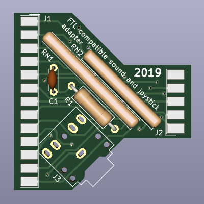
Ah, of course, duh, I totally blanked on that. That's what I get for looking at electronic schematics in the middle of the night. Yes, the only common integrated R2R networks are indeed thru-hole, and that was indeed what was used in the Covox. With the size limitations he was working with, he couldn't use something like that, it needed to be SMD. So, it was a space constraint. So obvious to me now. I hate making simple mistakes like that in thought. Although, it seems like given the space remaining in an LPT shaped dongle [the CVX4 is a good example, the PCB takes up the entire space one could use for a simple dongle shaped adapter), one could use a larger PCB (but maybe making larger, custom shaped PCB's was harder back then?)

I agree with the amp design, I don't know what he was thinking, but, the original designer's pedigree is in electronics, and sound/speech systems in particular (actually, despite being in his 80's now, he still works as the senior design engineer for a company that produces professional grade telephony products, so he's still working in the field all this time later. He's pretty amazing. Probably one of the last of the "old school" engineers still out there). I'm sure he has a reason, I just don't have the education to understand what it was. Now it makes me want to sit down and crunch enough information to try and noodle it out. I might have to ask a friend of mine. He's a master at this sort of thing, and has a special love of reverse engineering (...he's just a little... 'eccentric'...).

I did the math, and if the resistors in the packs are within 0.1% tolerance of each other, and the other resistor pack, it would essentially create 9+ bits of precision, so you could actually lose one bit, and still be +8-bit, (or 0.2% for almost exactly 9-bits of precision, and as a result 8-bits with the loss of one for volume control). We can't really know what the LSB tolerance is in this design because we'd need to know the variance between the resistors inside each pack, and the variance between the packs themselves to be able to calculate that. So, theoretically, it is possible, but, in practice, rather unlikely, since that is a very tight tolerance between discreet pieces that were never meant for such tight tolerance.

When you assemble it, the proof will be in the pudding. If it respond to the software for the SoundJr. exactly like the original, then that confirms the schematic is 100% and you've managed to salvage the working theory of one of the best pieces of tech that represents this group of devices from the dustbin of time.

Once the SoundJr. RE is confirmed. It would be interesting to try and integrate FTL detection into it (it's just a jumper wire from what I understand, so it could be controlled with a simple hardware switch on the side of the device) as well as the DSS into a single device. A 3-in-1 adapter (Enhanced Covox Speech Thing/FTL/DSS [using a 3 position switch for selection]) that can be powered just from the LPT port and drive headphones directly would really be an accomplishment. Something no one else has done. I'd imagine to fit it all in there, you'd have to switch to a more Covox housing (square board) rather than the SoundJr. housing.