VOGONS


Clone of Amstrad's Adlib clone

Topic actions

First post, by Benedikt

User metadata
Rank Oldbie
Rank
Oldbie

Hi!

This is a WIP clone of Amstrad's Adlib clone. Some 90% of the work are still missing, but I don't currently have time for that. Maybe someone else is interested?

There's this thread on the card. The circuitry should be relatively close to a combination of an Adlib card with a different amplifier and an Analog Input Card / Game Control Adapter.

amstrad_adlib_pcb_mockup.png
Filename
amstrad_adlib_pcb_mockup.png
File size
71.23 KiB
Views
3019 views
File license
Fair use/fair dealing exception

Repository on Github

Reply 2 of 34, by Benedikt

User metadata
Rank Oldbie
Rank
Oldbie

Well, if you already have the photos, feel free to upload them!

All I have is random photos from the web that I can't upload here and photos from this forum.

Reply 3 of 34, by gca

User metadata
Rank Member
Rank
Member

Yeah I guess just uploading them won't cause any harm. Here you go.

Attachments

  • sound2.jpg
    Filename
    sound2.jpg
    File size
    266 KiB
    Views
    2916 views
    File license
    Fair use/fair dealing exception
  • sound1.jpg
    Filename
    sound1.jpg
    File size
    270.03 KiB
    Views
    2916 views
    File license
    Fair use/fair dealing exception

Reply 4 of 34, by kompas-rus

User metadata
Rank Newbie
Rank
Newbie

Hello everyone, friends, I am very interested to make this board. About half a year ago, I started drawing this board, but I don’t have enough information about some of the connections, if there is such an opportunity, I can call the connection and you can check the multimeter. And also I will forgive you to give me photos in very good quality from different angles.

Last edited by kompas-rus on 2019-11-13, 04:05. Edited 2 times in total.

Reply 5 of 34, by Benedikt

User metadata
Rank Oldbie
Rank
Oldbie

Welcome to VOGONS, kompas-rus and thank you for the photos, gca!

You should be able to derive a lot of the connections from a combination of the reverse-engineered Adlib schematics (here), the manual of the Game Control Adapter (here) and application notes from the datasheets of the TDA7233 and LM324 amplifier chips.
Since I don't own the original card, this is all I can contribute for the time being. My KiCAD files are linked in the first post, but as you can see, they do not contain any traces, yet.

Reply 6 of 34, by kompas-rus

User metadata
Rank Newbie
Rank
Newbie
Benedikt wrote:

Welcome to VOGONS, kompas-rus and thank you for the photos, gca!

You should be able to derive a lot of the connections from a combination of the reverse-engineered Adlib schematics (here), the manual of the Game Control Adapter (here) and application notes from the datasheets of the TDA7233 and LM324 amplifier chips.
Since I don't own the original card, this is all I can contribute for the time being. My KiCAD files are linked in the first post, but as you can see, they do not contain any traces, yet.

Adlib, friend is an example circuit, but it doesn’t fit in the area of the decoder, I also look at the SB1 circuit and the SB2 circuit that I drew, but this is only "GAME PORT" from 558. I need more, I won’t do it fast.

Reply 8 of 34, by Benedikt

User metadata
Rank Oldbie
Rank
Oldbie
kompas-rus wrote:

Hello everyone, friends, I am very interested to make this board. About half a year ago, I started drawing this board, but I don’t have enough information about some of the connections, if there is such an opportunity, I can call the connection and you can check the multimeter. And also I will forgive you to give me photos in very good quality from different angles.

You were interested in the address decoder portion of the card, right? I ran into similar problems with a few connections that were obscured by the components, but I have since been able to figure them out via re-engineering.

This should be it:

address_decoding.png
Filename
address_decoding.png
File size
19.09 KiB
Views
2650 views
File license
Fair use/fair dealing exception

Reply 9 of 34, by kompas-rus

User metadata
Rank Newbie
Rank
Newbie
Benedikt wrote:
You were interested in the address decoder portion of the card, right? I ran into similar problems with a few connections that […]
Show full quote
kompas-rus wrote:

Hello everyone, friends, I am very interested to make this board. About half a year ago, I started drawing this board, but I don’t have enough information about some of the connections, if there is such an opportunity, I can call the connection and you can check the multimeter. And also I will forgive you to give me photos in very good quality from different angles.

You were interested in the address decoder portion of the card, right? I ran into similar problems with a few connections that were obscured by the components, but I have since been able to figure them out via re-engineering.

This should be it:

address_decoding.png

Friend, this was done 6 days ago, I'm interested in "SILK" to maintain the authenticity of the board, I can not write PM.

Reply 10 of 34, by root42

User metadata
Rank l33t
Rank
l33t
kompas-rus wrote:

Friend, this was done 6 days ago, I'm interested in "SILK" to maintain the authenticity of the board, I can not write PM.

As usual, you can use one of the general threads (e.g. 'what retro activity did you do today?') to gain some karma, so you can so PMs.

YouTube and Bonus
80486DX@33 MHz, 16 MiB RAM, Tseng ET4000 1 MiB, SnarkBarker & GUSar Lite, PC MIDI Card+X2+SC55+MT32, OSSC

Reply 11 of 34, by kompas-rus

User metadata
Rank Newbie
Rank
Newbie
root42 wrote:
kompas-rus wrote:

Friend, this was done 6 days ago, I'm interested in "SILK" to maintain the authenticity of the board, I can not write PM.

As usual, you can use one of the general threads (e.g. 'what retro activity did you do today?') to gain some karma, so you can so PMs.

Friend i don't wanna do spam
Someone write to this person in PM, say that I will forgive a photo of good quality. Re: Clone of Amstrad's Adlib clone

Reply 12 of 34, by Benedikt

User metadata
Rank Oldbie
Rank
Oldbie

I have relayed your request.

The answer is that the card is currently installed in a system that is stored away somewhere and that taking additional photos would consequently involve too much work.

Besides, I'm not exactly sure what exactly you cannot see on the existing pictures, particularly the ones in the thread that I linked in the initial post.
Are there any component designators you cannot read?
Unless you in all seriousness try to import the raster images as silk-screen, directly, the existing photos should be adequate.

Reply 13 of 34, by kompas-rus

User metadata
Rank Newbie
Rank
Newbie
Benedikt wrote:
I have relayed your request. […]
Show full quote

I have relayed your request.

The answer is that the card is currently installed in a system that is stored away somewhere and that taking additional photos would consequently involve too much work.

Besides, I'm not exactly sure what exactly you cannot see on the existing pictures, particularly the ones in the thread that I linked in the initial post.
Are there any component designators you cannot read?
Unless you in all seriousness try to import the raster images as silk-screen, directly, the existing photos should be adequate.

The quality of the photos presented here is poor, I can’t copy "Silk", I tried to find a nice font, but I can’t find it, I think it would be better if the photo is in good quality, I can make a perfect map clone, I did it many times before .

Reply 14 of 34, by Benedikt

User metadata
Rank Oldbie
Rank
Oldbie

Unless I find any errors, this is the finished design:

rendering_front.jpg
Filename
rendering_front.jpg
File size
116.94 KiB
Views
2393 views
File license
Fair use/fair dealing exception

The routing and silk screen are similar but not identical to the original because I found them ugly.
There's obviously no Amstrad brand logo on it, either, and I've shifted the DA15 connector in a position that is compatible with Keystone bracket 9200-3.

Reply 17 of 34, by Benedikt

User metadata
Rank Oldbie
Rank
Oldbie
kompas-rus wrote on 2020-01-02, 14:31:

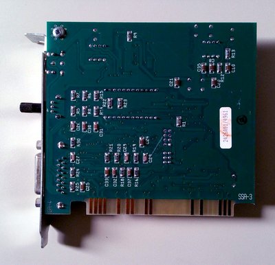
Benedikt But this is a bad clone of the card, I would like the appearance of a 100% original board. I also ordered 10 boards, but I will have them in February.

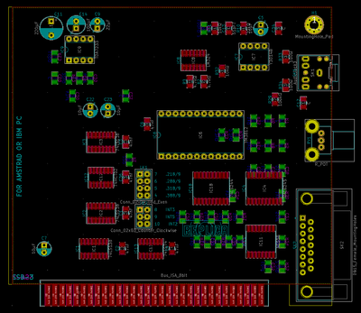
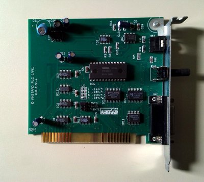
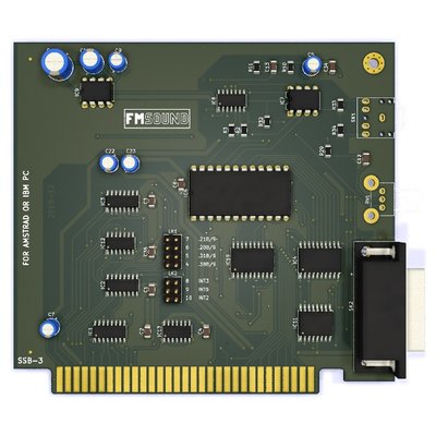
It is a trade-off between a good clone and a good card. The original card looks like the person who created it didn't even care about clean routing and well aligned traces. The data bus, for instance, is all over the place.

The other modifications are practicality-related:

  • Smaller hole pitch for most electrolytic capacitors – The original was using 2mm pin pitch with 5mm hole pitch, which just looks awkward
  • The DA15 socket has been shifted by a few mm, because drilling two holes in a DA15 bracket is easier than creating a new bracket from scratch
  • The footprint for the audio jack has been changed to that of the switched version (more pins), so that you can populate it with whichever version you can get your hands on

As I said earlier, I found the routing and silkscreen ugly, that's why I tidied them up while keeping the overall layout largely identical.
If you have a different taste and prefer a 100% accurate replica, that's obviously equally legitimate.

In the end of the day, independently creating two different accurate replicas of the same card would be kind of pointless.

Reply 18 of 34, by root42

User metadata
Rank l33t
Rank
l33t

I think the changes make sense. Especially making it compatible with the Keystone bracket is useful. Getting custom brackets is a pain in the behind. If I didn't have so many homebrew soundcards already, I would build this one as well. 😀

YouTube and Bonus
80486DX@33 MHz, 16 MiB RAM, Tseng ET4000 1 MiB, SnarkBarker & GUSar Lite, PC MIDI Card+X2+SC55+MT32, OSSC

Reply 19 of 34, by dreamblaster

User metadata
Rank Oldbie
Rank
Oldbie

The changes make sense, good looking project !

Visit http://www.serdashop.com for retro sound cards, video converters, ...
DreamBlaster X2, S2, S2P, HDD Clicker, ... many projects !
New X2GS SE & X16GS sound card : https://www.serdashop.com/X2GS-SE ,
Thanks for your support !