VOGONS


Reply 160 of 834, by polpo

User metadata
Rank Member
Rank
Member

Sorry about any confusion there about U2. I originally designed the board with a 74LVC244 in mind, but now use a SN74CB3T3245 because it has a compatible pinout and near zero propagation delay like the SN74CB3T3245 mux/demux chips. The KiCad project and the interactive BOM still have the 74LVC244 part, though. I’ll update them both!

Reply 161 of 834, by appiah4

User metadata
Rank l33t++
Rank
l33t++

Before I solder the pico down... It can be flashed while in circuit right?

Retronautics: A digital gallery of my retro computers, hardware and projects.

Reply 162 of 834, by polpo

User metadata
Rank Member
Rank
Member

Yes, it can be flashed while in circuit but you will need to tie the RESET ISA line to ground. See the programming section of the build guide for which pin it is: https://github.com/polpo/picogus/wiki/Buildin … amming-the-pico

Note that the next release of the firmware and pgusinit.exe will allow the Pico to also be flashed from DOS after initial programming. 🙂

Reply 163 of 834, by appiah4

User metadata
Rank l33t++
Rank
l33t++

By the way..

IMG_20230119_001508_1600x1200.jpg
Filename
IMG_20230119_001508_1600x1200.jpg
File size
371.96 KiB
Views
1482 views
File license
CC-BY-4.0

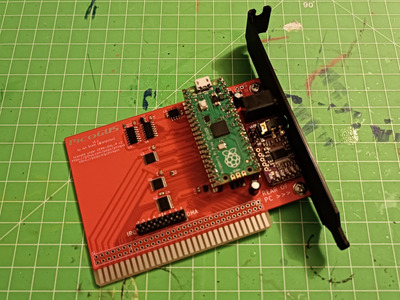
It is not as neat as what @Shreddoc made, but in my defense it was my first SMT soldering attempt and I caused no bridges.

Retronautics: A digital gallery of my retro computers, hardware and projects.

Reply 165 of 834, by Shreddoc

User metadata
Rank Oldbie
Rank
Oldbie
appiah4 wrote on 2023-01-18, 22:09:

By the way..

IMG_20230119_001508_1600x1200.jpg

It is not as neat as what @Shreddoc made, but in my defense it was my first SMT soldering attempt and I caused no bridges.

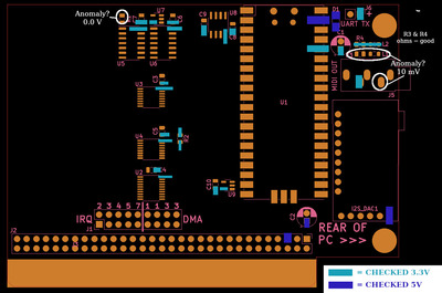
Well it proves the rule that "what looks good, might not BE good" ... because my first attempt got the dreaded no PicoGUS detected! message from PGUSINIT, when the moment-of-truth arrived. Not entirely a surprise, given that I haven't done something like this before.

I am doing some rudimentary multimeter testing in-situ, checking to see which components are successfully receiving 3.3v and 5v. I may post results later, in an effort to ask for further guidance, if there is any to be had. Or, failing that, just try again with PCB #2. 😀

Reply 166 of 834, by polpo

User metadata
Rank Member
Rank
Member

Uh oh... one quick question, I assume you're using one of the GUS firmwares? The current release of pgusinit.exe only detects the card if it's emulating a GUS. If you want to do the bare minimum test of the card's functionality in GUS mode, you can start DEBUG and run the following commands, assuming you're using GUS base port 240. If you're using a different base port, adjust the 343 in the below commands to 323 for base 220 or 363 for base 260...

o 343 55
i 343

If it prints 55, the card is at least working well enough to read from and write to the ISA bus.

Also the UART out pin outputs debugging messages using 5V TTL serial signaling at 115200 baud, if you have a TTL to USB serial cable handy, so you can see if the Pico is initializing correctly.

Reply 167 of 834, by appiah4

User metadata
Rank l33t++
Rank
l33t++

Well, I haven't even flashed the pico yet so no system/driver testing from me..

Soon, though.

Retronautics: A digital gallery of my retro computers, hardware and projects.

Reply 168 of 834, by Shreddoc

User metadata
Rank Oldbie
Rank
Oldbie
polpo wrote on 2023-01-19, 04:12:

Uh oh... one quick question, I assume you're using one of the GUS firmwares?

I think so. I haven't used a Pico before, but I followed your flashing instructions, and things seemed to go how I expected during the process. However, I need to have another look in detail. edit: I had another look, and I'm confident that I'm flashing it correctly.

polpo wrote on 2023-01-19, 04:12:
The current release of pgusinit.exe only detects the card if it's emulating a GUS. If you want to do the bare minimum test of th […]
Show full quote

The current release of pgusinit.exe only detects the card if it's emulating a GUS. If you want to do the bare minimum test of the card's functionality in GUS mode, you can start DEBUG and run the following commands, assuming you're using GUS base port 240. If you're using a different base port, adjust the 343 in the below commands to 323 for base 220 or 363 for base 260...

o 343 55
i 343

If it prints 55, the card is at least working well enough to read from and write to the ISA bus.

Also the UART out pin outputs debugging messages using 5V TTL serial signaling at 115200 baud, if you have a TTL to USB serial cable handy, so you can see if the Pico is initializing correctly.

When trying the DEBUG routine in DOS, I got "FF" back. So that would seem to be a negatory!, on that front.

Regarding the TTL-to-USB cable, I can cheaply source one not too far away, so I may add one to the arsenal, for learning's sake.

I've tested all that I currently can, with my basic meter and rudimentary knowledge. What I found, for whatever it's worth :

card_check.jpg
Filename
card_check.jpg
File size
222.69 KiB
Views
1347 views
File license
Public domain

I'm not too worried, I have spare parts to try again, and it was a good physical learning process.

Reply 169 of 834, by MJay99

User metadata
Rank Member
Rank
Member

Not saying it necessarily needs to be that, also, but I remember having a similar issue with detection on the very first attempt, too. I can't exactly say what fixed it, but pgusinit also just reported not finding the card. So, I basically tried reflashing it (with another address version) and not cutting the power instantly after uploading the firmware, setting a different IRQ / DMA (important: it needs two jumpers for the DMA) and a proper ultrasnd variable. Retrying afterwards, it instantly got detected and I actually never went back to see what really did cause it.

Of course, if this doesn't do anything, it really might also be hardware / solder related.

Reply 170 of 834, by appiah4

User metadata
Rank l33t++
Rank
l33t++

OK, you had me until the ULTRASND variable.. Time to google SET ULTRASND..

EDIT: Oh, ok, I need to add SET ULTRASND=240,7,7,3,3 to my AUTOEXEC.

EDIT2: This card is NOT PnP at all, is it? ie. No support for/from UNISOUND right?

EDIT3: Which reminds me, why is the Address selection a part of the flashed ROM and not a jumper on the card?

Retronautics: A digital gallery of my retro computers, hardware and projects.

Reply 171 of 834, by appiah4

User metadata
Rank l33t++
Rank
l33t++
Pickle wrote on 2023-01-19, 02:47:

anyone have an extra pcb?

I do, but I'm located in Turkey so shipping would be an issue. It's probably cheaper for you to order directly from JLCPCB a batch of five and wait a month than get one from me and wait a week.. and maybe pay more..

Retronautics: A digital gallery of my retro computers, hardware and projects.

Reply 172 of 834, by MJay99

User metadata
Rank Member
Rank
Member

It's not PnP, though I wish it were able to be initialized by unisound, too, of course 😀 But that would mean the Picogus would need to implement PnP also and be able to deal with DRQs, etc. directly - I'm guessing the limited GPIOs are the reason it's not there.

As for the address, I think this might solve itself a little better with the card becoming flashable from the DOS... then you could just upload a proper firmware for the desired address from there (even though it's more invasive than just setting an address). Otherwise, address decoding might be doable in hardware and with a spearate jumper block (e.g. schlae's snark barker would have a usable schematic) - I just don't know if there are other dependencies making it unfeasable for the Picogus.

Reply 173 of 834, by appiah4

User metadata
Rank l33t++
Rank
l33t++

The only reason I could think of was not enough GPIO pins so what there is is only ehough to do the bus transfers and IRQ DMA selection.. Which is strange but it is what it is 😀

Retronautics: A digital gallery of my retro computers, hardware and projects.

Reply 174 of 834, by polpo

User metadata
Rank Member
Rank
Member
appiah4 wrote on 2023-01-19, 10:36:
OK, you had me until the ULTRASND variable.. Time to google SET ULTRASND.. […]
Show full quote

OK, you had me until the ULTRASND variable.. Time to google SET ULTRASND..

EDIT: Oh, ok, I need to add SET ULTRASND=240,7,7,3,3 to my AUTOEXEC.

EDIT2: This card is NOT PnP at all, is it? ie. No support for/from UNISOUND right?

EDIT3: Which reminds me, why is the Address selection a part of the flashed ROM and not a jumper on the card?

It should be SET ULTRASND=240,3,3,7,7 – it's port,dma,dma,irq,irq.

Yeah, no PnP at all. It does feel strange having the exact opposite type of configuration as the GUS (jumpers for IRQ/DMA vs. jumpers for address) but address decoding is done entirely in firmware on the PicoGUS. The way things are is the result of a number of tradeoffs: number of GPIOs, flexibility of emulation, and BOM cost & availability of components.

Choosing the address with a jumper and using traditional hardware address decoding would have meant being locked down to only supporting a few addresses. A card like the GUS that supports a variety of addresses (GUS, AdLib, MPU-401) has to have pretty complex address decoding – it was implemented in like 4 GALs on the early versions and in a custom ASIC (the GF1D1) on later ones. Matching that would have meant using more discrete logic, GALs, or a CPLD which would have increased the BOM cost and ultimately not save any GPIOs – with address decoding in firmware and addresses being muxed with data, it's only 2 more GPIOs to support the full 10-bit IO address space. And then you can emulate any card you want instead of having the address ranges that you can decode baked into hardware! Firmware is temporary, hardware is forever...

The limited GPIOs also meant I had to use jumpers to choose the IRQ (IRQx) and DMA (DRQx, DACKx) signals to route to the Pico. Having this configurable via software would have meant more hardware on the card and even more GPIOs that I didn't have.

MJay99 wrote on 2023-01-19, 12:13:

As for the address, I think this might solve itself a little better with the card becoming flashable from the DOS... then you could just upload a proper firmware for the desired address from there (even though it's more invasive than just setting an address). Otherwise, address decoding might be doable in hardware and with a spearate jumper block (e.g. schlae's snark barker would have a usable schematic) - I just don't know if there are other dependencies making it unfeasable for the Picogus.

I am wrapping up the next version of the firmware which will support firmware flashing and setting the GUS port in DOS using pgusinit.exe. Here is a preview video where the card is in GUS mode, I then upload the AdLib firmware onto the card, and then run a program that uses AdLib: https://www.youtube.com/watch?v=5HkKBqUo1q0
Reply 175 of 834, by polpo

User metadata
Rank Member
Rank
Member
Shreddoc wrote on 2023-01-19, 05:42:

I've tested all that I currently can, with my basic meter and rudimentary knowledge. What I found, for whatever it's worth :

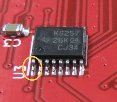
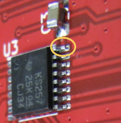
This all looks normal to me... I'm guessing you have a hidden solder bridge under the legs of one of the TSSOP chips. Have you checked that there is no continuity between all legs that are adjacent on the 3 TSSOPs?

Also, check these joints on the top edge of U3. It's hard to tell from the photos, but it doesn't look like they're fully connected:

Attachments

  • u3-2.jpg
    Filename
    u3-2.jpg
    File size
    100.76 KiB
    Views
    1227 views
    File license
    Public domain
  • u3-1.jpg
    Filename
    u3-1.jpg
    File size
    155.13 KiB
    Views
    1227 views
    File license
    Public domain

Reply 176 of 834, by MJay99

User metadata
Rank Member
Rank
Member
polpo wrote on 2023-01-19, 15:29:

I am wrapping up the next version of the firmware which will support firmware flashing and setting the GUS port in DOS using pgusinit.exe. Here is a preview video where the card is in GUS mode, I then upload the AdLib firmware onto the card, and then run a program that uses AdLib: https://www.youtube.com/watch?v=5HkKBqUo1q0
Now that's something even better..! 😁

Reply 177 of 834, by Shreddoc

User metadata
Rank Oldbie
Rank
Oldbie

GUS-like card detected. 😀

Many thanks for the pointers @MJay99 and @polpo ! I hit the card with a fresh set of eyes today, did the mentioned continuity tests, and refluxed and reflowed a few suspicious areas on the TSSOPs. It seems to have made the difference.

Time and further usage will tell if it's totally 100%, but I've just run (demoscene) Crystal Dreams II, Juice, and Unreal, and they sound great! Oh yeah baby.

Thanks a ton to Ian and the upstream contributors for making this kickass project.

Reply 178 of 834, by polpo

User metadata
Rank Member
Rank
Member

Awesome news! I’m glad you were able to fix it without having to build a second card. I’ll be getting the next firmware version out in the next couple days so there will be even more things that work!

Reply 179 of 834, by appiah4

User metadata
Rank l33t++
Rank
l33t++

Flashing the Raspberry Pico went smoothly, even though mine is (AFAICT) not a genuine part but rather a bootleg. Regardless, card is now ready for testing and hopefully I will have some good news soon as well 😀

@polpo would you like to share some beta firmwares so that I can start testing games for you using the latest DMA enhancements?

Attachments

Retronautics: A digital gallery of my retro computers, hardware and projects.