VOGONS


Reply 360 of 845, by MJay99

User metadata
Rank Member
Rank
Member

Unless you already did that: I'd personally blindly go over all pins in a drag-solder way with a lot of flux, before I'd even start investigating much.

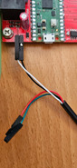
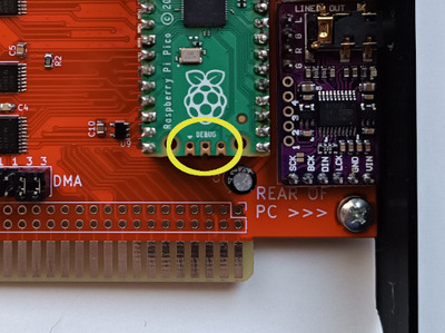
With a UART to USB adapter (at 115k baud) you could also attach to the pico and see if at least polpo's firmware comes up (this has actually helped me partly figure out what caused it to repeatedly crash on a differently routed card - seems that even slight noise on the reset line causes it to reboot).

If nothing of this helps and with an oscilloscope, you could check the activity on the pico's PIOs (maybe you can see which one isn't transmitting to/from the Pico.. but personally, I'd rather go and swap out the ICs part for part - that would be much less 'intelligent' usually but much quicker 😁

And btw: the issue could also be on the Pico side - a friend of mine somehow happened to create a bridge on the underside of the pico. Plus, there is also a slight possibility of a damaged Pico: I once had one with two broken IO pins.

And as always, of course, different people, different ideas and approaches... caveat emptor 😀

Reply 362 of 845, by MJay99

User metadata
Rank Member
Rank
Member
appiah4 wrote on 2023-07-17, 22:17:

The Pico in question seems to be a bootleg, not a genuine..

Oh, then they might come with a different onboard flash (which might then need a differently compiled firmware).
I also had some from Ali with a totally different pinout...

I haven't tried the picotool for the picogus, but with the pico not on this card, you could definitely flash the rp2040-doom firmware onto it and check if it successfully boots and replies via the picotool:
https://github.com/kilograham/rp2040-doom

If so, it should at least also be compatible with the picogus, at least in terms of the flash (overclocking and pinout could still be issues).

Reply 363 of 845, by Shreddoc

User metadata
Rank Oldbie
Rank
Oldbie
appiah4 wrote on 2023-07-17, 22:17:

The Pico in question seems to be a bootleg, not a genuine..

Does the Pico board respond, when connected to a PC with USB cable?

(for that, remember to temporarily connect the ISA reset line to ground, as per the build guide)

Reply 364 of 845, by appiah4

User metadata
Rank l33t++
Rank
l33t++

When I connect it to the PC I get two flashes on the status LED and that's it. When I hold BOOTSEL upon connecting it does come up as a USB storage device called RPI-RP2 though.

Retronautics: A digital gallery of my retro computers, hardware and projects.

Reply 365 of 845, by Shreddoc

User metadata
Rank Oldbie
Rank
Oldbie
appiah4 wrote on 2023-07-17, 22:39:

When I connect it to the PC I get two flashes on the status LED and that's it. When I hold BOOTSEL upon connecting it does come up as a USB storage device called RPI-RP2 though.

That seems like normal + expected behaviour, from the Pico board itself.

So, we can probably cross "Pico board is outright dead" off our list of possibilities.

Reply 366 of 845, by appiah4

User metadata
Rank l33t++
Rank
l33t++

I'll take a good photo of the card in the morning so someone with sharper eyes can look at my solder work maybe 😀

Retronautics: A digital gallery of my retro computers, hardware and projects.

Reply 367 of 845, by polpo

User metadata
Rank Member
Rank
Member

MJay99 has some good suggestions. Connecting a TTL serial adapter up to the UART TX port on the PicoGUS can tell you if it's trying to boot. If you see it booting but pgusinit still fails, then something is preventing it from responding to bus events. See this post for how to poke at it with debug to see if works at all: Re: PicoGUS: ISA sound card emulator with Raspberry Pi Pico (Gravis Ultrasound, AdLib, MPU-401, Tandy, CMS)

One interesting failure mode is if IOCHRDY doesn't work - root42 ran into this on a stream of his where he was building a PicoGUS. AdLib firmware worked fine for playing music, pgusinit was not working reliably, and GUS emulation didn't work at all. He had a teeny tiny solder bridge on U9, the chip responsible for handling IOCHRDY.

Reply 368 of 845, by appiah4

User metadata
Rank l33t++
Rank
l33t++

Thanks polpo do I do the UART monitoring using the UART +/- pins while in the socket? How do I hook that up to a USB serial TTL adapter?

Here is a photo of the card..

Attachments

Retronautics: A digital gallery of my retro computers, hardware and projects.

Reply 369 of 845, by root42

User metadata
Rank l33t
Rank
l33t
polpo wrote on 2023-07-17, 23:57:

One interesting failure mode is if IOCHRDY doesn't work - root42 ran into this on a stream of his where he was building a PicoGUS. AdLib firmware worked fine for playing music, pgusinit was not working reliably, and GUS emulation didn't work at all. He had a teeny tiny solder bridge on U9, the chip responsible for handling IOCHRDY.

Ah yes. Those were good times!

YouTube and Bonus
80486DX@33 MHz, 16 MiB RAM, Tseng ET4000 1 MiB, SnarkBarker & GUSar Lite, PC MIDI Card+X2+SC55+MT32, OSSC

Reply 370 of 845, by root42

User metadata
Rank l33t
Rank
l33t
appiah4 wrote on 2023-07-17, 22:17:

The Pico in question seems to be a bootleg, not a genuine..

Judging from your photo the pico looks pretty genuine to me. Why do you think it isn't?

YouTube and Bonus
80486DX@33 MHz, 16 MiB RAM, Tseng ET4000 1 MiB, SnarkBarker & GUSar Lite, PC MIDI Card+X2+SC55+MT32, OSSC

Reply 371 of 845, by appiah4

User metadata
Rank l33t++
Rank
l33t++
root42 wrote on 2023-07-18, 07:08:
appiah4 wrote on 2023-07-17, 22:17:

The Pico in question seems to be a bootleg, not a genuine..

Judging from your photo the pico looks pretty genuine to me. Why do you think it isn't?

It came in a weird cheap packaging compared to mine, so I thought it was a bootleg or something..

Retronautics: A digital gallery of my retro computers, hardware and projects.

Reply 372 of 845, by MJay99

User metadata
Rank Member
Rank
Member

Does the LED of the card actually show any signs of life when inside the system, without being connected to a USB?
If not, the diode could accidentally be positioned the wrong way (or not making proper contact to the pad).

From the picture (which could also just be a lighting issue), it looks like C10 (100nF) and C8 (should be 1nF) might be swapped (judging from the slightly different color of the caps), but that probably shouldn't affect pgusinit - it might just let the psram be less stable (if at all).

I'd personally still suggest to go over all pins with quite a bit of flux and a clean solder iron tip for each row in order to even remove some solder.
From this image's perspective, the bridges on the tssops that theoretically could happen, sadly wouldn't show - in case they happen, they're often right at the body of the package, behind the pins.

Since you measured for shorts, though, I wouldn't expect bridges - but there still is the possibilty that a pin doesn't make proper contact with the pad underneath.
That you could try and measure also, or simply take out the big hammer and drag-solder them all 😁

As for the UART adapter (from Aliexpress), this is how mine would be connected:

uart.jpeg
Filename
uart.jpeg
File size
103.56 KiB
Views
1186 views
File license
CC-BY-4.0

And I do agree with root42, the Pico looks completely identical in layout to mine - so I wouldn't think they're fake / bootlegs, too.

Reply 373 of 845, by Daniël Oosterhuis

User metadata
Rank Member
Rank
Member
MJay99 wrote on 2023-07-17, 22:20:

I also had some from Ali with a totally different pinout...

Just curious, is the situation in some countries w/re availability of Pi Picos bad enough that AliExpress Picos would be cheaper?
Over here in the Netherlands, I pay about four bucks per Pico from an authorized RPi dealer who has loads of 'em, which AE couldn't possibly compete with, on top of the dealer being far more reliable for legitimate parts.

That said, I haven't heard of, or seen knockoff Picos myself yet.
Can't imagine there'd be a huge market for them, given the absolute dirt-cheapness of the RPi2040 and Pico boards (though again, maybe in some countries the situation is different?).

sUd4xjs.gif

Reply 374 of 845, by appiah4

User metadata
Rank l33t++
Rank
l33t++
MJay99 wrote on 2023-07-18, 07:25:
Does the LED of the card actually show any signs of life when inside the system, without being connected to a USB? If not, the […]
Show full quote

Does the LED of the card actually show any signs of life when inside the system, without being connected to a USB?
If not, the diode could accidentally be positioned the wrong way (or not making proper contact to the pad).

From the picture (which could also just be a lighting issue), it looks like C10 (100nF) and C8 (should be 1nF) might be swapped (judging from the slightly different color of the caps), but that probably shouldn't affect pgusinit - it might just let the psram be less stable (if at all).

I'd personally still suggest to go over all pins with quite a bit of flux and a clean solder iron tip for each row in order to even remove some solder.
From this image's perspective, the bridges on the tssops that theoretically could happen, sadly wouldn't show - in case they happen, they're often right at the body of the package, behind the pins.

Since you measured for shorts, though, I wouldn't expect bridges - but there still is the possibilty that a pin doesn't make proper contact with the pad underneath.
That you could try and measure also, or simply take out the big hammer and drag-solder them all 😁

As for the UART adapter (from Aliexpress), this is how mine would be connected:
uart.jpeg

And I do agree with root42, the Pico looks completely identical in layout to mine - so I wouldn't think they're fake / bootlegs, too.

When the card is in the ISA slot, the Pico LED flashes briefly and the DAC LED stays on the whole time. I also checked the 3V3 and 3V3_EN pins of the Pico it is getting +3.31V from the ISA slot so power delivery is not the issue.

To confirm, the +/- from the UART header goes to the TX/RX of the USB TTL adapter right? What speed does the PicoGUS communicate at?

I reflowed the ICs twice, but I'll go over them again tonight. 🤞

I'll also rmove C10 and C8 and add new caps in their place to verify they are the correct value.

C4 and C5 also don't look properly aligned, I'll shift those into place as well. Could be the issue?

Last edited by appiah4 on 2023-07-18, 07:42. Edited 4 times in total.

Retronautics: A digital gallery of my retro computers, hardware and projects.

Reply 375 of 845, by MJay99

User metadata
Rank Member
Rank
Member
Daniël Oosterhuis wrote on 2023-07-18, 07:28:

Can't imagine there'd be a huge market for them, given the absolute dirt-cheapness of the RPi2040 and Pico boards (though again, maybe in some countries the situation is different?).

There's definitely no need to go there at all. Personally, I was looking to get some 16MB ones (for that doom project above), which aren't available from e.g. Digikey or Mouser. In that context I ordered a couple of different models and versions, simply for testing, finding that different types of flash or different pinouts can happen, resulting in the need to either adapt the footprints or compile for a different flash.

So, indeed, better get them from your regular suppliers.

Reply 376 of 845, by Shreddoc

User metadata
Rank Oldbie
Rank
Oldbie

I noticed in the above image that the 3 end pins of the Pico appear to be unconnected to the PicoGUS PCB.

IMG_20230718_091222.jpg
Filename
IMG_20230718_091222.jpg
File size
83.07 KiB
Views
1133 views
File license
Public domain

I don't know if they are supposed to be connected to be PicoGUS PCB or not (there are pads), or if this causes any running issue.

Last edited by Shreddoc on 2023-07-18, 08:07. Edited 1 time in total.

Reply 377 of 845, by MJay99

User metadata
Rank Member
Rank
Member
appiah4 wrote on 2023-07-18, 07:32:

C4 and C5 also don't look properly aligned, I'll shift those into place as well. Could be the issue?

I'd expect this to be only about cosmetics, they do look like they're soldered to the pad.
Usually I wouldn't even expect a missing 100nF cap to be too much of an issue.

Reply 378 of 845, by MJay99

User metadata
Rank Member
Rank
Member
Shreddoc wrote on 2023-07-18, 08:00:

I noticed in the above image that the 3 end pins of the Pico appear to be unconnected.

Hmm, the debug pins (left and right) aren't connected to anything else on the PCB, as far as I remember.
The middle pin is GND and connected to the other GNDs - so I wouldn't really expect this to be an issue.

Looking closer at the Pico, there seems to be flux residue between the pins, especially on the right side of the Pico - it's a bit hard to tell from the image, but maybe a cleaning (or checking for shorts) there might also be an idea?

Reply 379 of 845, by MJay99

User metadata
Rank Member
Rank
Member
appiah4 wrote on 2023-07-18, 07:32:

When the card is in the ISA slot, the Pico LED flashes briefly and the DAC LED stays on the whole time. I also checked the 3V3 and 3V3_EN pins of the Pico it is getting +3.31V from the ISA slot so power delivery is not the issue.

That indeed sounds ok and rules out the diode.

appiah4 wrote on 2023-07-18, 07:32:

To confirm, the +/- from the UART header goes to the TX/RX of the USB TTL adapter right? What speed does the PicoGUS communicate at?

One pin of the header is TX, the other simply GND. My adapter (PL2303HX) wants: black to be GND, white to be TXD (for the unused ones: red would be +5V, green is RXD). My connection worked with 8N1@115200 baud.