@Delphius - Thanks for attaching that capture of your scope. If you have the reset line disconnected from the ISA bus, you'll need to tie it to ground so it's not floating. In your photo on the Github issue, I see you have a jumper header already on it, so just closing that should be simple. If RESET is left floating, I wouldn't be too surprised by the "activity" that you're seeing on it. I've seen simply touching the board being enough to "drive" the floating reset line high or low.
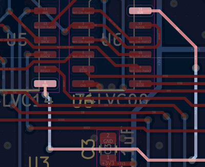
All in all, I'm really stumped by the behavior you're seeing on your build, especially in that you see the MPU firmware working just fine. Code that uses the DAC shouldn't really affect the RESET or RUN lines since physically the DAC signals are far away and isolated to the part of the board under the DAC module. Code-wise, there really shouldn't be much of a difference either. Nothing's really sticking out to me as a culprit so I'm totally at a loss. Very early on in the development of PicoGUS, I did run into spurious resets caused by certain bus activity which caused me to start using a 74LVC14 Schmitt trigger inverter, and then later switching to a 74AHC14, and now in my latest hardware designs, pulling reset down and RUN up, adding a capacitor, etc.
Socketing the Pico is totally fine – all of the "Femto" PicoGUSes are socketed and I've not had any reports of issues with them.


