VOGONS


First post, by ales

User metadata
Rank Newbie
Rank
Newbie

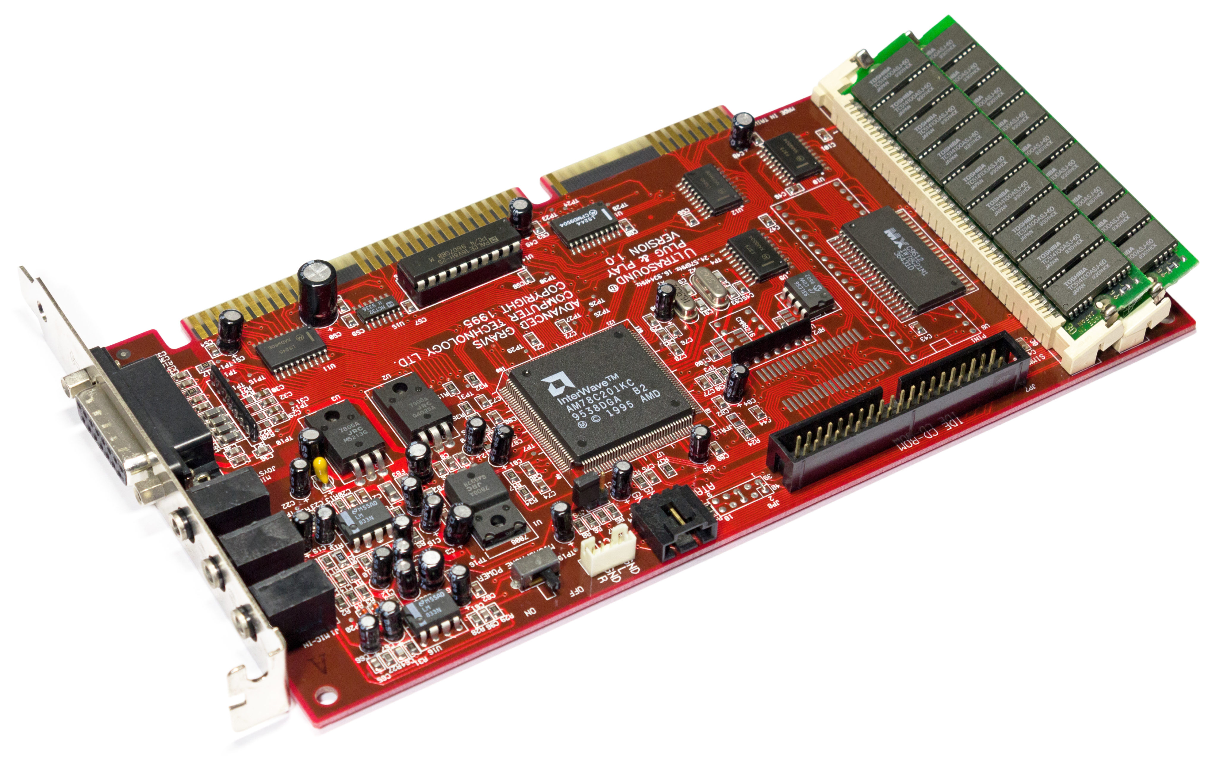
Hi everyone. I recently acquired this beat up GUS PnP and I'm wondering if it can be brought back to life. I've had trouble finding relevant information about the hardware, so I thought I'd ask here for help.

From comparing the card with images online, I see the following (I marked each item in the image):

  1. Broken latch on SIMM2 socket
    Probably not a big deal. I could replace the socket once I get the card working.
  2. Missing capacitor C48
    Purely based on size appearance, it could be the same cap as C49 and C51, which are 47 uF, 16V
  3. Missing capacitor C11
    Again, maybe it's the same as C10 (10 uF, 25V), but really no idea.
  4. Missing chip 93C66
    There seem to be two variants of the card. One with this EEPROM chip, and another with a different (smaller) chip in the overlapping position marked U6.
    My card has neither, which I'm assuming is a problem. Or is it? Is this the (optional) MIDI patch-set memory that is only present on the PnP Pro?
    If this chip is required, can I flash it after installing it on the card, or would I need to flash it upfront? Where do I obtain the right content for it?

I'd appreciate any ideas or pointers. Is it a stupid idea trying to revive the card, given that someone apparently had a reason to treat it like trash?
Thanks!

Attachments

Reply 1 of 38, by weedeewee

User metadata
Rank l33t
Rank
l33t

1. yep
2. decoupling capacitors, so your guess is likely good
3. ? no idea, might be another decoupling cap on a lower voltage line
4. this eeprom normally contains the PnP info, if i'm not mistaken. No idea if it will work without it.

Right to repair is fundamental. You own it, you're allowed to fix it.
How To Ask Questions The Smart Way
Do not ask Why !
https://www.vogonswiki.com/index.php/Serial_port

Reply 2 of 38, by MJay99

User metadata
Rank Member
Rank
Member

There's lots of information about the eeprom by thermalwrong here:
Re: ARGUS Project thread - now accepting pre-orders (for north/south American and Europe)

And the necessary tool for programming the 93c66b can be found in shock's doc package here:
download/file.php?id=101255

(flash it with: pnpmap XXXX.ROM)

I don't have the card in front of me, but I can dig out mine and check the values a little later.

Reply 3 of 38, by cyclone3d

User metadata
Rank l33t++
Rank
l33t++

For the "broken" latch, it looks to me like the spring metal latch is just bent. You should be able to bend that back into place very easily. The tiny bit of broken plastic makes no difference whatsoever.

Yamaha modified setupds and drivers
Yamaha XG repository
YMF7x4 Guide
Aopen AW744L II SB-LINK

Reply 4 of 38, by 640K!enough

User metadata
Rank Oldbie
Rank
Oldbie

C48 is 47µF 16V.

C11 is 10µF 25V.

On the original card, U6 is a 93LC66/P, but any appropriate replacement should work (see Thermalwrong's post, linked previously). This contains the Plug and Play resource map, as described. It is possible to get the card to a functional state without it, but it isn't usually a good idea to try running it that way. Furthermore, the original part is still available and inexpensive, and it is easy to write the contents while it is installed on the card. Once that is done and you have the full Gravis software package installed under DOS, you may want to use PNPCFG to disable features that you will not be using, as they consume resources, and generally cause more trouble than they are worth.

As already mentioned, the metal retaining clip on the SIMM socket can be gently bent back into position, likely without any problems. It would be much easier than having to replace the socket.

From the picture, it also looks like C90 has taken a beating. You may want to look at it more closely, to make sure it hasn't been damaged. Just in case, C90 is 1µF 50V.

For the sake of completeness, the instrument bank ROM is U8.

From the photo, it doesn't look like it was intentionally mistreated, just stored in a careless way, until someone realised that it could fetch a good price on the used market. I offer C48 as evidence. Unless that capacitor blew up so spectacularly that that is all that's left, it looks like it was physically smashed from the board while it was carelessly thrown in a box (or someone who didn't know what they were doing attempted "repairs"); there is still a little piece left.

If you attempt to fix it, please let us know how it goes. These tend to be somewhat rare and expensive, so it would be nice to know that it is working again.

Reply 5 of 38, by ales

User metadata
Rank Newbie
Rank
Newbie

Thank you so much for all the quick replies! This info is super helpful, and you strengthened my hope that I might get it working again. I owned this card in the '90s and have regretted getting rid of it, so I'd be thrilled to save this one and be able to enjoy it again.

From the photo, it doesn't look like it was intentionally mistreated, just stored in a careless way

Yes, it was probably stored carelessly. What you cannot see in the photo is that the board is also slightly bent.
Anyway, if it were only the yanked C48 and SIMM socket, I would totally agree that someone just mistakenly stepped on it or something. But I cannot explain the missing C11 and especially the EEPROM chip which seem to have been extracted. Maybe they knew that the GUS was dead and took the chip for reuse. But I'm remaining hopeful and will definitely update you after I get the parts and attempt the repair.

Thanks again! 😀

Reply 6 of 38, by MJay99

User metadata
Rank Member
Rank
Member

If it's truly (been) bent, there is a chance of connection issues at the Interwave - but nothing a careful resoldering with enough flux wouldn't fix then, as long as the pads aren't totally torn off.

Otherwise the card really doesn't look that bad to me - the lower left corner looks like physical damage to me, C11 like it was snipped off and the eeprom really does look a bit like someone needed it somewhere else... in today's marked, that would be insane, but who knows since when this card has been laying around 😀

I've also had a look at my card and 640K!enough's values are the same as on mine.

In case you can't get it to work with these smaller fixes, please don't throw it away - find someone who can have a closer look at e.g. the Interwave, then (and if necessary, even that can be replaced). And I concur, please keep us updated about things 😀

Reply 7 of 38, by 640K!enough

User metadata
Rank Oldbie
Rank
Oldbie

I had another look at the photo, and I am now firmly convinced that somebody made an attempt at repairing this specimen, then eventually gave up. The burning question now is: what led them to need to "repair" it in the first place? Add another critical question: did they try to test it after "fixing" it?

Seriously, take a really close look, then tell me what you see.

Spoiler

Am I entirely nuts, or is the ROM soldered on the wrong way around?

The LS244 (U13) looks like it might not be original, as well (Chinese-market re-marked "NOS"? Chip borrowed from somewhere else?). It clearly doesn't resemble the other discrete ICs, and the soldering job also doesn't look quite the same.

Definitely, unless I am stupidly mistaken, the ROM will have to be corrected. Then, look at each and every electrolytic capacitor, and make sure they haven't been damaged (there are a few that look strange, but it could just be a reflection from when you took the picture).

If you think you might need some help, it may be useful to at least specify the country in which you live (in your profile).

Reply 8 of 38, by ales

User metadata
Rank Newbie
Rank
Newbie

Using this photo as reference, it looks like everything that is present on my card is in the right place and orientation. And just like on mine, the LS244 on this photo also has lighter lettering than other ICs. It's honestly very similar to my card, even to the detail of the mic connector being a little askew towards the line-in one. So maybe it's not all that bad and it's just how these were originally produced.

gus-perspective-e1486143509291.jpg
(the image is hi-res, open it in new tab for full detail)

I will however follow your advice and inspect the individual components more closesly. You're right that the C90 looks like it got a hit from the top with something sharp.

Which one is the ROM?

Reply 9 of 38, by MJay99

User metadata
Rank Member
Rank
Member

The ROM is the SOP package with the big 'MX' letters on it (u8).

What's very interesting now is: they are indeed similarily oriented in those two pictures above, BUT: on the card in front of me, it is turned by 180 degrees (apparently as 640K!enough is also seeing it on his side).
And what's even more fun: a while ago I found that my ROM isn't showing up in unisound and I did swap it for another and back, to no avail, also checking the latches on the way and in the end thinking the interwave might have gotten damaged.
I didn't even bother to think the ROM could have been installed the wrong way in the first place - so that is something I'll now investigate in the near future. Even more if 640K!enough could confirm that he's also seeing an IC turned 180 degrees on his card and maybe not showing up on init... 😀

Attachments

Reply 10 of 38, by root42

User metadata
Rank l33t
Rank
l33t
MJay99 wrote on 2022-07-05, 09:07:

What's very interesting now is: they are indeed similarily oriented in those two pictures above, BUT: on the card in front of me, it is turned by 180 degrees (apparently as 640K!enough is also seeing it on his side).
And what's even more fun: a while ago I found that my ROM isn't showing up in unisound and I did swap it for another and back, to no avail, also checking the latches on the way and in the end thinking the interwave might have gotten damaged.
I didn't even bother to think the ROM could have been installed the wrong way in the first place - so that is something I'll now investigate in the near future. Even more if 640K!enough could confirm that he's also seeing an IC turned 180 degrees on his card and maybe not showing up on init... 😀

The picture you are showing has the notch of the ROM at the top. This aligns with the silkscreen of the DIP package outline of the alternate ROM. I would guess that the silkscreen for the SMD ROM is the same, so the ROM is correctly oriented. The earlier picture has no visible notch, so I am unsure which way it should face.

YouTube and Bonus
80486DX@33 MHz, 16 MiB RAM, Tseng ET4000 1 MiB, SnarkBarker & GUSar Lite, PC MIDI Card+X2+SC55+MT32, OSSC

Reply 12 of 38, by root42

User metadata
Rank l33t
Rank
l33t
Oetker wrote on 2022-07-05, 09:17:

Ales's second picture doesn't have a notch on the SMD ROM, but the OP's picture does, and it's facing the wrong way... how strange

You're right. OP's ROM is definitely in the wrong way I would say.

YouTube and Bonus
80486DX@33 MHz, 16 MiB RAM, Tseng ET4000 1 MiB, SnarkBarker & GUSar Lite, PC MIDI Card+X2+SC55+MT32, OSSC

Reply 13 of 38, by MJay99

User metadata
Rank Member
Rank
Member

Couldn't resist verifying it right away, VCC and GND for the IW78C21M1 seem to be in the correct spots on my card - so it's probably just another coincidence that my Interwave seems to have an issue there.
That means: both the Hi-res picture and the picture in the first post show the ROM in an apparently wrong orientation (since at a first glance, also the routing on the card seems similar).

Reply 14 of 38, by ales

User metadata
Rank Newbie
Rank
Newbie

Wow, this is so weird. You're right, all images of the card online have the ROM in the opposite direction. Except the one that I posted as reference! And the notch is there, just not very well visible in the lighting of that picture. Just check the top view of the card on the page from which I took the image: https://vccollection.ru/?page_id=2938

How is this even possible? The only reasonable thing I can think of is that the chip on my card and the one of the ref. picture share the exact same signage. The other cards out there have different ones. Maybe the one that I have has reversed internals for some reason?

Reply 15 of 38, by weedeewee

User metadata
Rank l33t
Rank
l33t

Just adding my 2cents...

a photo of my guspnp.

Attachments

Right to repair is fundamental. You own it, you're allowed to fix it.
How To Ask Questions The Smart Way
Do not ask Why !
https://www.vogonswiki.com/index.php/Serial_port

Reply 16 of 38, by 640K!enough

User metadata
Rank Oldbie
Rank
Oldbie

If we ignore the ROM IC itself and pay attention to the board, we see that the traces are exactly the same as all of the other Version 1.0 boards of this type that have been shown. Based on that, we know how the ROM should be oriented (pin-1 notch at the top, as indicated by the silk-screen layer). So, unless we are to assume that there was a batch that left the Macronix production line with everything as it should be, except that the plastic top cover was fitted the wrong way around, orientation notch and all, and that the contract assembly company for Gravis compensated and installed them anyway, then there is no way it isn't backwards. I suppose it's possible, but I would be surprised.

Reply 17 of 38, by Tiido

User metadata
Rank l33t
Rank
l33t

The pins look soldered, so some shenanigans have happened.

T-04YBSC, a new YMF71x based sound card & Official VOGONS thread about it
Newly made 4MB 60ns 30pin SIMMs ~
mida sa loed ? nagunii aru ei saa 😜

Reply 18 of 38, by ales

User metadata
Rank Newbie
Rank
Newbie

OK I finally managed to obtain and fit the missing parts (C11, C48, and 93LC66/P). I haven't touched the ROM yet. When I insert the card into the PC (which normally works), it doesn't even POST. Sadly I don't have a speaker attached to hear any error beeps, but I do see all of the keyboard lights being turned on indefinitely.

The card is dead cold - none of the ICs heat up. Is there any diagnostics that I can do to get an idea of where it's failing?

Reply 19 of 38, by weedeewee

User metadata
Rank l33t
Rank
l33t

Just had another look at your photo and besides the rom being reversed (pretty sure that removing it will still allow the card to work if it was working to begin with, ofcourse without synthesizer music) , it looks like the pins of the 7905 are loose.
Fixing the 7905 solder joints likely will not solve your current problem

The fact that it is stopping your computer from booting, will imply that it is somehow messing some signals on the ISA bus up. this could be as simple as one of the logic/buffer ic's or worst case the interwave chip itself.

Right to repair is fundamental. You own it, you're allowed to fix it.
How To Ask Questions The Smart Way
Do not ask Why !
https://www.vogonswiki.com/index.php/Serial_port