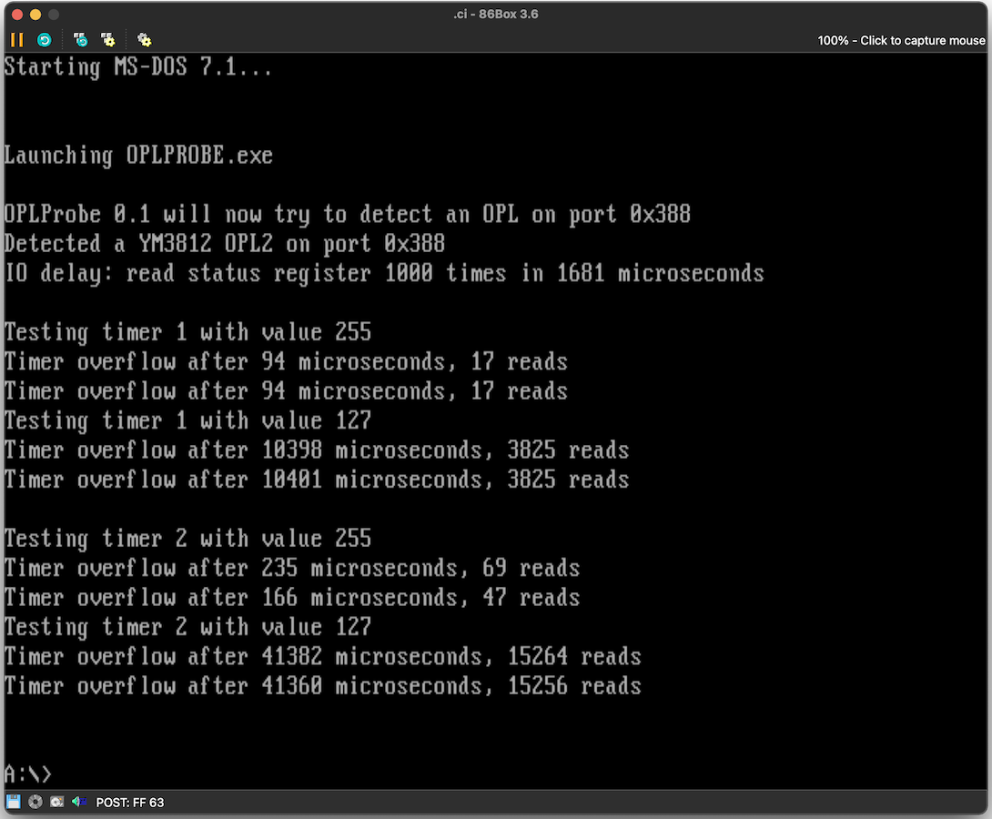
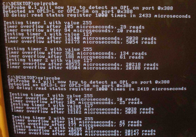
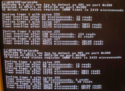
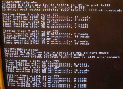
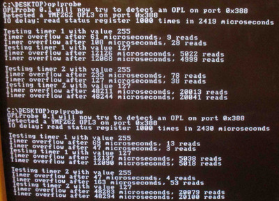
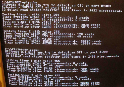
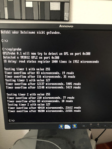
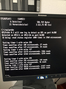
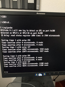
I posted 5x results into the attachments. I have no OPL2 to play with for the time being. Timer 1 with 255 is highly variable with its result on my test machine (1.4GHz PIII machine with VIA chipset)
Anyway for completeness sake :
The timer circuitry runs off YM's sample rate which for
OPL2 is MCLK / 72 = 3579545 / 72 = 49715.90277....Hz (20.11428... µs)
OPL3 has 4x higher MCLK but it is divided down by 4x so end result is same as OPL2
OPL3L is a little trickier, MCLK there is 33868800Hz and internal sample rate slightly different from OPL2/3 : 33868800 / 684 = 49515.78947...Hz (20.19557...µs), which is then decimated into standard 44100Hz rate (33868800 / 768) for final audio output.
OPL2/3 Timer 1 counts every 4x YM output cycles (80.457153...µs), Timer 2 every 16x YM output cycles (321.82861...µs).
OPL3L Timer 1 has (80.78231...µs), Timer 2 every 16x YM output cycles (323.12925...µs).
I'm pretty sure the 255 is a typo, though it is difficult to gauge from the results I got as 255 result on Timer 1 is all over the place.
Timer 1 period is supposed to be (72 * 4) * (256 - T1val) clock cycles
Timer 2 period is (72 * 16) * (256 - T2val) clock cycles
Timer value of 0 should be longest possible count and using that will determine if 255/256 difference is actually there, if it is 255, 0 will show much different result. (it is not something I have personally tested) so perhaps you should make a test with 0 value aswell.