VOGONS


First post, by Frunzl

User metadata
Rank Newbie
Rank
Newbie

Hi,

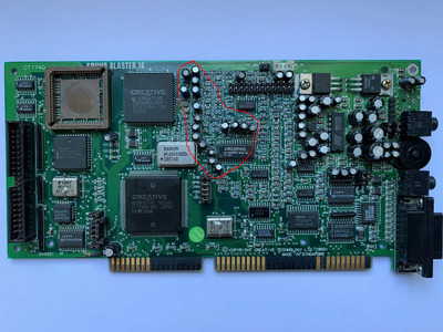
I recently found a cheap SB16 CT1740 with DSP 4.04, which I would very much like to save.

The seller said that it was partially working, but that the left channel was dead, so I hoped it might be an easy fix, maybe a dead Cap in the amplifier circuitry.
Turns out, it's not easy at all.

At first, it was dead silent on the left channel (both FM and samples). Oddly enough, sound came through when I wiggled the jack a little. So I thought again, easy, someone ripped out the jack and it just needs resoldering or replacement at worst. But even after replacing it, I simply could not get any sound from the left channel, except when putting a little downward pressure on the line-in connector/jack.

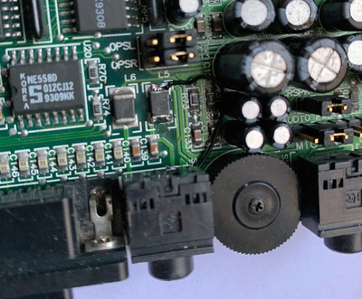
After measuring a little bit in the area, it turns out that inductor L5 was burnt or cracked and didn't make a connection.

Since, as far as I know, these only serve as fuses against ESD damage, I just bypassed it. But I was a little worried that there could be further damage. And sure enough: Now the card is outputting on both channels, but FM sound on the left channel (again) remains extremely low in volume, barely audible. Samples on the other hand play fine on both channels.

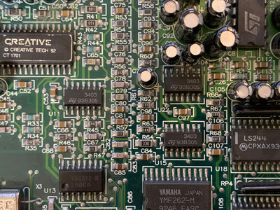
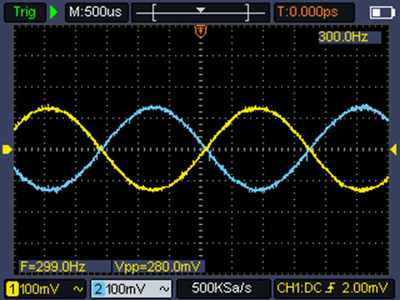
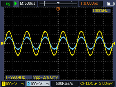
I wanted to isolate the problem further and traced the FM signals from the YMF chip all the way to the DAC (YAC512) output pins with a scope. At this stage, both channels are still coming through with equal amplitude, so I guess the OPL and DAC are fine.

I believe, the signal is then supposed to go to the mixer chip (CT1745) and then to the line-out (or amp, if activated).

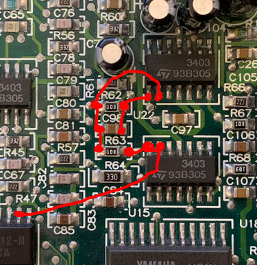
Now, this is unfortunately where my progress stopped, since I cannot find a pinout for the CT1745. I think, I have identified the output pins for both channels and at this stage, the output is already low on the left channel for FM.

So the problem could be the mixer chip itself, but since I was too unskilled to locate the input pins until now, I cannot be sure. There are a bunch of electrolytic caps right next to the mixer, but again since I couldn't locate the input pins, I do not know if one of them might be the problem here. I removed a few candidates, but they all tested fine.

I would really like to avoid having to replace all the caps (except for the amp, which I don't need) only for the chip to turn out bad.

Therefore, after this long intro (sorry), my questions: does someone know the pinout of the CT1745? Alternatively, which caps could be located between the DAC output and the mixer input? Any thoughts would be appreciated.

By the way, I know, C41 is missing on the photo. This is because I removed it, not relevant in this case.

Thanks!

Attachments

  • Unbenannt-1.jpg
    Filename
    Unbenannt-1.jpg
    File size
    396.28 KiB
    Views
    1497 views
    File comment
    Inductor L5
    File license
    Fair use/fair dealing exception
  • IMG_1338.jpg
    Filename
    IMG_1338.jpg
    File size
    677.94 KiB
    Views
    1497 views
    File license
    Fair use/fair dealing exception

Reply 1 of 36, by Tiido

User metadata
Rank l33t
Rank
l33t

DAC output goes to some opamps first for filtering, gain adjust and to mix with WB header sound. Pins 42 and 43 should be the ones carrying FM+MIDI mix into the mixer chip. The problem is most likely in one of the tiny capacitors near the mixer chip, they are easy to bend and it is possible one has bent enough that it ripped internally, and then pushed back. Visually it'll look ok but inside is actually broken.

T-04YBSC, a new YMF71x based sound card & Official VOGONS thread about it
Newly made 4MB 60ns 30pin SIMMs ~
mida sa loed ? nagunii aru ei saa 😜

Reply 2 of 36, by Frunzl

User metadata
Rank Newbie
Rank
Newbie
Tiido wrote on 2022-11-03, 12:33:

DAC output goes to some opamps first for filtering, gain adjust and to mix with WB header sound. Pins 42 and 43 should be the ones carrying FM+MIDI mix into the mixer chip. The problem is most likely in one of the tiny capacitors near the mixer chip, they are easy to bend and it is possible one has bent enough that it ripped internally, and then pushed back. Visually it'll look ok but inside is actually broken.

Thanks, that helps a lot, I will probe 42 and 43 and see what I get.

And I guess, I will recap the region next to the Mixer..

Reply 3 of 36, by Tiido

User metadata
Rank l33t
Rank
l33t

I hope this is the issue, you can measure and see if both sides of the capacitors are roughly equal and if one isn't you know the source of the problem. Anyway good luck ~

T-04YBSC, a new YMF71x based sound card & Official VOGONS thread about it
Newly made 4MB 60ns 30pin SIMMs ~
mida sa loed ? nagunii aru ei saa 😜

Reply 4 of 36, by Frunzl

User metadata
Rank Newbie
Rank
Newbie

Replaced all the caps in the red circle below. no improvement...

All caps were within specs. Well I guess it's good, I didn't kill it for good in the process (or is it..)

Attachments

  • red.jpg
    Filename
    red.jpg
    File size
    888.55 KiB
    Views
    1437 views
    File license
    Fair use/fair dealing exception

Reply 5 of 36, by Tiido

User metadata
Rank l33t
Rank
l33t

Including the C41 which is missing on the circled area ? I actually missed it on the initial photo, that one is 100% definitely needed 🤣

T-04YBSC, a new YMF71x based sound card & Official VOGONS thread about it
Newly made 4MB 60ns 30pin SIMMs ~
mida sa loed ? nagunii aru ei saa 😜

Reply 6 of 36, by Frunzl

User metadata
Rank Newbie
Rank
Newbie
Tiido wrote on 2022-11-03, 16:30:

Including the C41 which is missing on the circled area ? I actually missed it on the initial photo, that one is 100% definitely needed 🤣

🤣, yes, including that one 😀

Reply 7 of 36, by Tiido

User metadata
Rank l33t
Rank
l33t

Then you have to start going over the passives. R42 looks like it has a scratch on it but the photo is not having high enough resolution to really tell. Since you have a scope it shouldn't take too much effort to start going back from the mixer chip inputs to whatever opamp is in the signal path, though I admit the routing is terrible on this card and difficult to follow as it is on all other SB and AWE cards 🤣. I have this card somewhere in my stash and if I can find it, I'll take some looks myself. I recently moved and much of my stuff is still in towers of boxes 🤣

T-04YBSC, a new YMF71x based sound card & Official VOGONS thread about it
Newly made 4MB 60ns 30pin SIMMs ~
mida sa loed ? nagunii aru ei saa 😜

Reply 8 of 36, by Frunzl

User metadata
Rank Newbie
Rank
Newbie

I was afraid, I would have to do that 😀

Thanks for your help until this point. Do you think that the small smd caps also have a significant probability of failure (I actually don’t think so)? Otherwise, I would focus on the resistors, especially any 0 Ohm ones, which may have blown during an ESD event. Does that make any sense?

Also, the Opamps in question are the 3403, correct? I am wondering why there are four of them on the board.

Attachments

Reply 9 of 36, by Tiido

User metadata
Rank l33t
Rank
l33t

I don't think there was any ESD damage, just physical abuse. When the board is flexed enough, any of the surface mounted parts can suffer, and big stuff is most likely to as force around them will be greatest.

Yeah, these are the opamps, with standard quad opamp pinout. You only need to probe the outer pins to see if anything is imbalanced and you have identified the area to look at.

T-04YBSC, a new YMF71x based sound card & Official VOGONS thread about it
Newly made 4MB 60ns 30pin SIMMs ~
mida sa loed ? nagunii aru ei saa 😜

Reply 10 of 36, by Frunzl

User metadata
Rank Newbie
Rank
Newbie

After measuring and probing and so on, I discovered that for the right channel, which is working, the signal travels from the DAC to the input pins of opamp U15 (directly next to the OPL). It then leaves the opamp again with some phase shifting going on and seems to arrive at the output pins of U22. Why the output pins? I don't know... U22 has no visible input on the -in pin and is connected to ground with the +in pin.

On the left channel, the phase shifted signal is not generated and instead the U22 left channel output pin is silent. But inexplicably, the -in pin does show a signal (which is not the case for the right channel), namely the original in-phase signal but at exactly half the amplitude. By the way, the difference in frequency visible on the screenshot is just because I had both channels on different test tones (R, 300 Hz; L 1000Hz) to be able to differentiate.

Summary

For U15, both channels are the same:
+in: DAC output
-in: connected to the output pin next to it
out: Same as DAC output, nice and strong

For U22, right channel:
+ in: ground
- in: no signal
out: phase shifted signal

For U22 left channel:
+in: ground
-in: original in-phase signal with exactly half the amplitude
out: no signal

I have no idea how to interpret this... I removed and checked the components involved (R61, R62, R63 and C98 for the left channel) and they are all ok. The connections are also fine but I think it's clear that the problem occurs somewhere here.

Attachments

Reply 11 of 36, by mkarcher

User metadata
Rank l33t
Rank
l33t
Frunzl wrote on 2022-11-04, 19:04:

After measuring and probing and so on, I discovered that for the right channel, which is working, the signal travels from the DAC to the input pins of opamp U15 (directly next to the OPL). It then leaves the opamp again with some phase shifting going on and seems to arrive at the output pins of U22. Why the output pins? I don't know... U22 has no visible input on the +in pin and is connected to ground with the -in pin.

You seem to have mixed +in an -in. If you swap them, it is the basic setup of using an operational amplifier as inverting amplifier. This setup works by connecting the "non-inverting input" (often called +in) to ground, and connecting the input signal via a resistor (the input resistor) to the "inverting input" (often called -in), as well as connecting the output via another resistor (the feedback resistor) to the inverting input, too. The idea is that the Op-Amp tries to output a voltage in a way that both inputs have the same voltage. As +in is grounded, -in is actively pulled to ground, too. As the operational amplifier sinks or sources no significant current on -in, the current through the input resistor equals the current through the feedback resistor. This implies that if the feedback resistor has three times the resistance of the input resistor (for example), the output voltage will be three times as high as the input voltage so that the currents get equal. In your case, the input and output resistors seem to be equal, so you get exactly the same voltage (but inverted) at the output pin that you had before the input resistor.

Frunzl wrote on 2022-11-04, 19:04:

On the left channel, the phase shifted signal is not generated and instead the U22 left channel output pin is silent. But inexplicably, the +in pin does show a signal (which is not the case for the right channel), namely the original in-phase signal but at exactly half the amplitude. By the way, the difference in frequency visible on the screenshot is just because I had both channels on different test tones (R, 300 Hz; L 1000Hz) to be able to differentiate.

As I explained above, the -in pin of U22 (you still seem to have them mixed up, at least you did so consistently) pin is connected to the output of U15 via an input resistor and the output of U22 is connected to the input pin via the feedback resistor. In your case, the output of U22 is stuck at ground, so the input resistor and the feedback resistor yield a 1:1 voltage divider, so you observe half the amplitude at -in of U22. This makes perfect sense, but you need to find out why the output of U22 is stuck at ground. It's not just open, it's really hard ground. If the output of U22 were not connected to anything, you would get the full output of U15 at -in of U22. I guess that using a continuity tester, you will find the output of U22 dead short connected to ground - and that's where your signal disappears. I'm not implying U22 is broken and shorting the output pin - while that might be the case, anything connected to the trace that leaves U22 and connects the signal towards the mixer chip might be the case of the short circuit.

Reply 13 of 36, by Frunzl

User metadata
Rank Newbie
Rank
Newbie

"Unfortunately", the U22 output is not shorted to ground (6 MOhm)...

By the way, below are the connections, stupidly drawn.

Attachments

  • red2.jpg
    Filename
    red2.jpg
    File size
    1.08 MiB
    Views
    1275 views
    File license
    Fair use/fair dealing exception

Reply 14 of 36, by Frunzl

User metadata
Rank Newbie
Rank
Newbie
mkarcher wrote on 2022-11-04, 19:25:
Frunzl wrote on 2022-11-04, 19:04:

If the output of U22 were not connected to anything, you would get the full output of U15 at -in of U22.

Are you certain about that? At this point, I tend to believe that the problem is within U22.

Interesting: DC voltage at the output pins that work correctly is +2.5 or -2.5 V, whereas on the faulty one it is -4.2 V (input voltage is correct at +5 or -5V).

Reply 15 of 36, by mkarcher

User metadata
Rank l33t
Rank
l33t
Frunzl wrote on 2022-11-04, 22:09:
mkarcher wrote on 2022-11-04, 19:25:
Frunzl wrote on 2022-11-04, 19:04:

If the output of U22 were not connected to anything, you would get the full output of U15 at -in of U22.

Are you certain about that? At this point, I tend to believe that the problem is within U22.

Interesting: DC voltage at the output pins that work correctly is +2.5 or -2.5 V, whereas on the faulty one it is -4.2 V (input voltage is correct at +5 or -5V).

So you are getting -4.2V constant with very little AC signal on it at the output of U22? This means U22 pulls its output as negative as it can with -5V on the negative supply. U22 is supposed to pull its output negative only if +in is at a lower voltage than -in. +in is supposed to be connected to ground, -in is at the average between +2.5V output of U15 and -4.2V output of U22, which is -0.85 volts. Check these voltages directly at the operational amplifier pins. I'm also inclined to believe that the problem is likely related to U22, but we need to find out whether the issue is inside U22 or one of the pins of U22 doesn't make contact to the PCB. For example, symptoms like on your card are common if -in left is unconnected.

Reply 16 of 36, by Frunzl

User metadata
Rank Newbie
Rank
Newbie
mkarcher wrote on 2022-11-04, 22:36:
Frunzl wrote on 2022-11-04, 22:09:
mkarcher wrote on 2022-11-04, 19:25:

Are you certain about that? At this point, I tend to believe that the problem is within U22.

Interesting: DC voltage at the output pins that work correctly is +2.5 or -2.5 V, whereas on the faulty one it is -4.2 V (input voltage is correct at +5 or -5V).

So you are getting -4.2V constant with very little AC signal on it at the output of U22? This means U22 pulls its output as negative as it can with -5V on the negative supply. U22 is supposed to pull its output negative only if +in is at a lower voltage than -in. +in is supposed to be connected to ground, -in is at the average between +2.5V output of U15 and -4.2V output of U22, which is -0.85 volts. Check these voltages directly at the operational amplifier pins. I'm also inclined to believe that the problem is likely related to U22, but we need to find out whether the issue is inside U22 or one of the pins of U22 doesn't make contact to the PCB. For example, symptoms like on your card are common if -in left is unconnected.

+in is connected to ground.
-in is indeed around -0.85V.

Unfortunately, I'm not made of opamps and I will have to order some replacements. But it would be great if that were the issue, since I have another SB16 (CT2290) with exactly the same symptoms and readings.

Reply 17 of 36, by Tiido

User metadata
Rank l33t
Rank
l33t

C105 next to the opamp has a little hole in top, I'm sure that cap is not happy. As far as the rest goes, interesting...
I located the boxes where my computer hardware is, but they are packed full with layers and layers of cards and for the time being, I will not disturb them yet. I know I have two such cards there that I can take closer looks at...

T-04YBSC, a new YMF71x based sound card & Official VOGONS thread about it
Newly made 4MB 60ns 30pin SIMMs ~
mida sa loed ? nagunii aru ei saa 😜

Reply 18 of 36, by Frunzl

User metadata
Rank Newbie
Rank
Newbie
Tiido wrote on 2022-11-05, 06:48:

C105 next to the opamp has a little hole in top, I'm sure that cap is not happy. As far as the rest goes, interesting...
I located the boxes where my computer hardware is, but they are packed full with layers and layers of cards and for the time being, I will not disturb them yet. I know I have two such cards there that I can take closer looks at...

Yes, the pinhole cap already crossed the rainbow bridge in the meantime 😀
But of course... didn't make any difference.

At least, the amplifier sounds much better, louder and cleaner for samples 🤣 after all that recapping 😀

But for now, I ordered some replacement opamps and I will report back asap when they arrive (probably EoW).

Reply 19 of 36, by mkarcher

User metadata
Rank l33t
Rank
l33t
Frunzl wrote on 2022-11-05, 19:37:

But for now, I ordered some replacement opamps and I will report back asap when they arrive (probably EoW).

There is one test you can do today: Lift the output pin of the relevant part of U22 from the PCB. If this makes the DC voltage at -in and the pad go up to positive voltages (possibly full 2.5V), you know for sure that U22 is responsible for pulling that trace down to -4.2V.