First post, by stanwebber
i notice a lot of aztech sound card pcbs have full header/jumper pins for all the rear audio jacks (at least that's what i think they are). it appears at the very least the following models share this feature:
pro 16 ii
waverider 32+
washington 16
multimedia pro 16
multimedia pro 16 iib-3d
pro 16 ii-3d pnp
nova 16 extra ii-3d
multimedia pro 16 abi/abo
waverider pro 32-3d
waverider pro 32-3d pnp
waverider platinum-3d pnp
multimedia pro-16 iiis+ pnp
if you're not familiar with what i'm talking about here is a reasonably hi-res image for reference. the pins are directly behind each respective rear jack and marked clearly on the pcb.
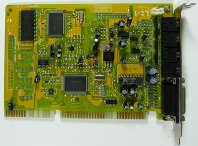
i presume these pins are connected in parallel to the contacts inside the audio jacks. what were these pins originally used for? they show up on so many aztech models they can't just be a one-off.
my question is: can i use these pins to connect to the front panel audio connectors? or will they cause noise or prevent the rear jacks from working? also, pin 1 is clearly identified for each jack. is there a standard pinout for generic pcb 3.5mm audio jacks?
