VOGONS


First post, by vstrakh

User metadata
Rank Member
Rank
Member

How's the mixing implemented on CT2940, and what are the common failure modes?
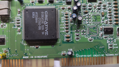
I have this card, it plays FM nicely in diagnose.exe, but the PCM (both 8/16 bit) are just barely above the noise floor.

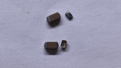
The card has lots of op-amps, mlcc caps and vias, something that might die or crack relatively easy, and I was hoping that since FM sounds is ok, then it's a matter of checking the PCM signal path.
But looking closer it appears that the CQM DAC op-amp (U7) output just goes back into CT2502 chip, so all the mixing happens internally. How it's possible to lose the PCM then? The mixerset shows voice/master levels close to the max.

Last edited by vstrakh on 2023-03-30, 14:42. Edited 1 time in total.

Reply 1 of 4, by vstrakh

User metadata
Rank Member
Rank
Member

Found and fixed 😀

I've checked the mlcc capacitors around the main CT2502 chip, it's quite often that analog devices expose some regulated reference voltages that needs filtering with external cap. I thought maybe it's dead and shorting the reference, that's why the levels are too low. No caps were shorted, but then I noticed two caps that are not going to ground, but instead something goes out of the chip and returns back to the chip after going though the caps. And I didn't like the thin sharp shadow on both caps visible only under extreme magnification.

See C125 and C124 on the photo:

PCM caps.jpg
Filename
PCM caps.jpg
File size
1.73 MiB
Views
483 views
File license
Public domain

Judging by their size they should measure somewhere around 100nF-300nF, but they didn't measure at all.
Desoldering them revealed the cause 😀

cracked caps.jpg
Filename
cracked caps.jpg
File size
689.01 KiB
Views
483 views
File license
Public domain

Replaced them with smallest capacity caps of same physical size (I had only 2uF in reach), and PCM is back 😀

So it would seem that the PCM is not routed to mixer internally on CT2940, it goes out of the DSP part of the chip only to return back to the mixer part of the chip. Perhaps it was just the way they've integrated multiple old chips on the same die - just packed IP together without redesigning, and routed connections outside of the package on the PCB.

Reply 3 of 4, by vstrakh

User metadata
Rank Member
Rank
Member

The U7 op-amp picks the output of either FM synthesizer.
Check the C67 and C52 electrolytics directly on the left from the U7, those are connecting U7 outputs to CT2502.
I had one electrolytic on 5v rail halfway torn by some side hit, same could happen with those too.

Also worth checking larger ceramic caps near the Yamaha DAC, C99 and C69, those are big and probably prone to cracking when the board is bent.

Reply 4 of 4, by georgel

User metadata
Rank Member
Rank
Member

Checked C99, C69 by live connecting in parallel 220nF capacitor without soldering and no FM sound is heard but I hear in the corresponding channel the mains interference so I guess the path to the output is fine including electrolytic caps and TDA1517P. Also tried replacing X3 crystal - no difference.