VOGONS


First post, by DerBaum

User metadata
Rank Oldbie
Rank
Oldbie

Some years ago i bought some kind of a reading device for blind people where you can scan a document with a scanner and let it read out loud.
It never worked right and went into "the pile".
Today i finally got around to have a look at it and i got it working (after modding the dallas clock and repair the HDD adapter).

I was suprised that the speech is fully synthesized by a "Infovox 500" card. I can find basically no usable information on this card on the internet (Pinout, Software etc...). The ROMS on the card seem to be language specific ( in my case german ).
The card has a Motorola 68k...
Here is a Video i took today of it speaking:
https://www.youtube.com/shorts/G01z7J_M3Uk

Now i have a fully working example to preserve at least the drivers and software... BUT there is some copy protection. I will figure out wich programs/drivers need the copy protection and maybe someone can help me to disable the dongle check before i post the software...
I will write up all findings properly in the coming posts.

Pictures:

2023-08-08 21.25.31.jpg
Filename
2023-08-08 21.25.31.jpg
File size
1.51 MiB
Views
419 views
File license
CC-BY-4.0
2023-08-08 21.25.41.jpg
Filename
2023-08-08 21.25.41.jpg
File size
1.97 MiB
Views
419 views
File license
CC-BY-4.0
2023-08-08 21.40.15.jpg
Filename
2023-08-08 21.40.15.jpg
File size
1.85 MiB
Views
419 views
File license
CC-BY-4.0
2023-08-08 21.40.22.jpg
Filename
2023-08-08 21.40.22.jpg
File size
1.61 MiB
Views
419 views
File license
CC-BY-4.0
2023-08-08 21.55.40.jpg
Filename
2023-08-08 21.55.40.jpg
File size
1.38 MiB
Views
419 views
File license
CC-BY-4.0

If you have any informations that are important to be preserved please post them here.

FCKGW-RHQQ2

Reply 1 of 5, by DerBaum

User metadata
Rank Oldbie
Rank
Oldbie

Thoughts...
I had planned to post the software and drivers but i figured out the company behind OpenBook (Software used on this system) still exists and is still lselling this software...
https://www.freedomscientific.com/products/so … tware/openbook/

Even the software version i want to preserve is nearly 30 Years old i really dont want to risk to violate copyrights...

My new plan is to make standalone driver packs without the OpenBook Software.

To use the talking card in pure dos is a lot of fun too. You can "copy" .txt files to the card and they are read.
...

Today i copied the HDD onto a CF Card. Everything still works like it should. If i disconnect the dongle the OpenBook software doesnt work anymore the rest works fine.
Another reason to just leave OpenBook out of the files i will preserve.

To get a working copy on my CF card was quite funky...
First i connected a floppy drive. then i booted the system from the hdd and created a boot floppy with some essential files like xcopy format and fdisk.
Fdisk doesnt want to mark partitions as active wich are not on drive c.
So i disconnected the HDD and connected my CF card as master. i booted the system from my freshly made floppy and Fdisk / Format the CF card. Now its bootable.
Then i jumpered the cf card as slave and the HDD as master and booted the system.
After that i xcopy everything from c (HDD) to d (CF card).
Done...

Now i have a copy of the whole system on a storage device wich is compatible with my modern machine.

The next step is to seperate the drivers and settings and set up a clean DOS system with everything needed to make the card talk and unerstand how it works...
Im also working on a pinout for the connector on the card...

2023-08-09 20.12.05.jpg
Filename
2023-08-09 20.12.05.jpg
File size
1.75 MiB
Views
368 views
File license
CC-BY-4.0
2023-08-09 20.27.51.jpg
Filename
2023-08-09 20.27.51.jpg
File size
1.42 MiB
Views
368 views
File license
CC-BY-4.0

FCKGW-RHQQ2

Reply 2 of 5, by Pierre32

User metadata
Rank Oldbie
Rank
Oldbie

What a cool piece of kit. Nice work diving in to get it going.

It doesn't look like the company offers legacy downloads of their software. In my non-legal opinion it really should be preserved. Personally I would archive it as a separate package to the drivers.

Reply 3 of 5, by DerBaum

User metadata
Rank Oldbie
Rank
Oldbie
Pierre32 wrote on 2023-08-09, 20:52:

What a cool piece of kit. Nice work diving in to get it going.

It doesn't look like the company offers legacy downloads of their software. In my non-legal opinion it really should be preserved. Personally I would archive it as a separate package to the drivers.

I have to find out how to get the personal data out of the system...
These things seem to be a nightmare for data security...
All documents ever scanned are stored and have to be deleted manually. There are over 160 documents in the data some of them contain personal data of the former owners.
The system is normally used without monitor and keyboard (the VGA and PS2 connector was locked behind a screwed on metal panel) from some buttons on the device.
I have to study the manual really hard to find out how to delete stuff.

FCKGW-RHQQ2

Reply 4 of 5, by DerBaum

User metadata
Rank Oldbie
Rank
Oldbie

Here is a dump of the 2 EEPROM chips U18 and U19.

Filename
Infovox500__v371_GE23_U18+U19.zip
File size
997.14 KiB
Downloads
26 downloads
File license
Fair use/fair dealing exception

The ZIP also contains this reference image:

VOXTALK500_ROMS.jpg
Filename
VOXTALK500_ROMS.jpg
File size
837.64 KiB
Views
286 views
File license
CC-BY-4.0

Its a "HI - LOW" situation where each rom has either the even or odd bytes.

Half the roms are empty... Probably because there is RAM in parallel to the ROMS where you can upload languages and settings into. Thats why there is a battery on the card...

Thats an awesome piece of engineering. My revision uses a 4 layer board with stacked ICs to save space... IN 1992!!

The person who designed this board with early 90s tools is a genius.

FCKGW-RHQQ2

Reply 5 of 5, by DerBaum

User metadata
Rank Oldbie
Rank
Oldbie

Lets talk a little bit about the connectors of the card.

2023-08-11 18.46.25.jpg
Filename
2023-08-11 18.46.25.jpg
File size
598.68 KiB
Views
253 views
File license
CC-BY-4.0

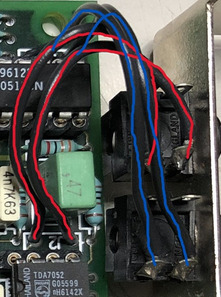
On my revision of the card the 3.5mm connecors are not soldered to the card itself. They are mounted on the bracket and use wires to connect to the circuit board.
On my card the connectors are not soldered to the points behind the mounting position. They have switched positions.

audio_out_voxtalk500.jpg
Filename
audio_out_voxtalk500.jpg
File size
90.5 KiB
Views
253 views
File license
CC-BY-4.0

Because i can not find any other picures of a card like mine i dont know if the positions are switched on all of them. But thats not really that important because you can simply follow the cables on your card and see wich one is wich.
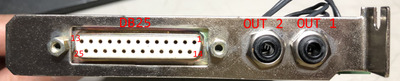
In my case the 3.5mm connector next to the DB25 connector (labeled as "OUT 2" in my picture) is a LINE OUT .
The 3.5mm connector towards the outside (labeled as "OUT 1" in my picture) is the AMPLIFIED OUTPUT.

IMPORTANT: Both 3.5mm connectors are only 2 position. They dont use the "ground sleeve" on a 3 position (TRS) plug. If you use a 3 position (TRS) plug the signals are on the "left" and "right" ring/tip.

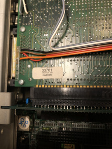
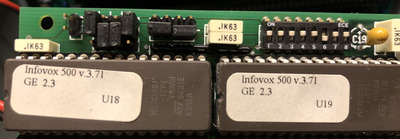
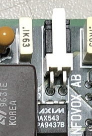
Another connector regarding the sound is this :

snd_in_infovox500.jpg
Filename
snd_in_infovox500.jpg
File size
35.44 KiB
Views
253 views
File license
CC-BY-4.0

Its located on the top edge of the card and in my case has a jumper across it.
The right Pin (in my picture) is just ground.
My best guess is that the left pin is an input for the PC speaker.
I have traced out the circuit and its origin is an input inside the amplification/mixing circuit.
As of righnt now i have not made any further experiments with this connector except of removing the jumper... wich resulted in no change at all (like expected).

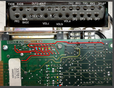
The DB25 connector was quite a challange to reverse engineer. Like i mentioned before the board is 4 layer where all layers are used for everything. That made it a little bit difficult to visually trace out the circuits. But in the end my trusty multimeter in beep mode and a LOT of time solved this issue. I probed every Pin of the DB25 connector to its origin in the circuit.
That was not only nice practice in patience but also told me a lot of the inner workings of the circuits.

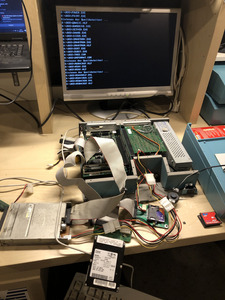
This picture is just for illustration puropses.

Screenshot 2023-08-13 190150.png
Filename
Screenshot 2023-08-13 190150.png
File size
1.33 MiB
Views
253 views
File license
CC-BY-4.0

It took several days of measuring, taking notes and experimenting to get to the point where i am now.
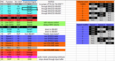
Maybe the informations in the picture above are interesting for a hand full of people who exactly want to know there each signal is coming from... But i condensed it down into a usable Pinout ... 😀

Screenshot 2023-08-13 190053.png
Filename
Screenshot 2023-08-13 190053.png
File size
58.13 KiB
Views
253 views
File license
CC-BY-4.0

Now lets see what each Pin is doing:

Starting with just voltages the card outputs:

Pin5 and Pin8 carry +5Volt
Pin22 is +12Volt
Pin23 is -12Volt
Pin7 and Pin11 are GROUND.

These voltages directly come from the ISA BUS connector.

Serial interfaces:
Part of the rescued drivers are some technical notes wich mention that the card can be controlled (and recieve text to speak) via a serial interface.
That explains why there are serial pins on the DB25 connector... But it doesnt explain why there are !3! serial interfaces on the connector.
The "Function" in my pinout picture are the names of the pins they connect to.
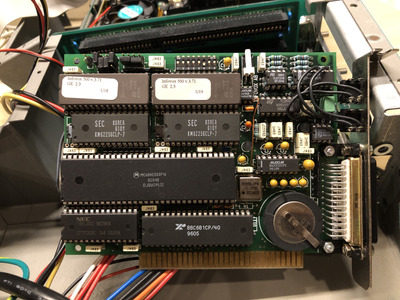
All 3 serial interfaces go to the 88C681 IC.
RX1 (Pin2) and TX1 (Pin3) / RX2 (Pin4) and TX2 (Pin5) are connected up to a MAX232 IC before they go to 88C681.
This converts the signals to standard RS232 signals before leaving and entering the card.
RXDB (Pin12) and TXDB (Pin13) are directly connected to 88C681.
At this point in time i know the serial interfaces exist but i have not done any experiments with them. Maybe i will try that in the future, then i will update the informations here.

General stuff:
Pin24 will mute the Audio when +5V is applied. The processing of the running job continues, just the Audio is muted.
Pin25 skips parts of the input buffer when shortly pulled to ground. At this point in time iam not sure if it clears the whole buffer and fills it completely new or just skips further ahead in the buffer. But that doesnt really matter too much...
Pin1 is connected up to an unpopulated jumper (JP10) on the backside of the card in its factory state. So it does nothing. The other side of the unpopulated jumper goes to a A4 input of a 74LS367 IC. No further experiments done now...
Pin14 is connected to the OP7 Pin of the 88C681 IC. This is an output. No further experiments done now...
Pin20 is not connected to anything.

Speed control:
You can control the speed of the spoken text with control characters in the document you want to read.
BUT you can use Pins on the DB25 connector to control the speed of the spoken output.
Pin 15, Pin16 and Pin17 are used to control the speed. I have called it the "speed modifier".
Depending of the combinations you pull these 3 Pins to ground you can make the speech slower in 4 steps and faster in 3 steps.
When none of the Pins are connected the system uses the base value . You can find all combinations in the pinout picture.

Volume control / Audio Output :
You can control the volume of the output with control characters in the document you want to read.
The DB25 connector also provides an interesting way to control the output volume.
Volume control is done "digitally" on the card itself. But only the control is digital... the stuff the digital signals control is analog... Very interesting solution.
The external volume has no effect on the volume you set via software... It is applied ON TOP of the software settings.
Pin18, Pin19 and Pin21 are used to control the volume. Depending on the combinations you pull these pins to ground you can have 8 different levels of volume.
When none of the pins are connected you have MAX volume. You can find all combinations in the pinout picture.

IMPORTANT: The volume settings only affect Pin9 (Line OUT1) and the 3.5mm connector (OUT1).
Pin8 (Line OUT2) and the 3.5mm connector (OUT2) are not affected by the volume settings.
Pin8 and Pin9 are unamplified LINE OUTS!!

-------------
Any Questions? Feel free to ask.
My next steps are to properly understand how to use the drivers make a driver pack and share it with you.
Maybe i build a breakout box for the DB25 connector with a shematic...

FCKGW-RHQQ2