VOGONS


Reply 20 of 30, by Jonas-fr

User metadata
Rank Member
Rank
Member

I just compared your pics from my card and I noticed that on mine jumper JP1 was set up on pin 1-2 while on yours it seems to be on pin 2-3. Also my external dipswitches are as follow (1 to 8, 0 is off, 1 is on) : 00110110

I still haven't got my hands on this card manual so I don't really know what this jumper do but I guess it would be easy for you to do a test by moving JP1 in the 1-2 position ?

Reply 21 of 30, by matze79

User metadata
Rank l33t
Rank
l33t

i have a similar Card in Stock, also from a Portable.

https://www.retrokits.de - blog, retro projects, hdd clicker, diy soundcards etc
https://www.retroianer.de - german retro computer board

Reply 22 of 30, by Jonas-fr

User metadata
Rank Member
Rank
Member

Would you be so kind as to dump the EPROM of it ? I fear mine might be corrupted

Attachments

Reply 23 of 30, by InbetweenDays

User metadata
Rank Newbie
Rank
Newbie

Good news -- the card is fixed (kinda) and working!
But first a big shout out of thanks to incanus and Jonas-fr (Is there a way to tag someone?) -- without your replies I'd not have known that a utility is required to switch output to the external VGA connector (which is a bit weird I must say).

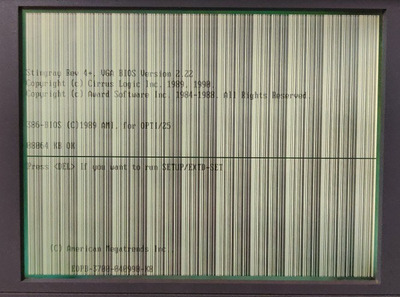
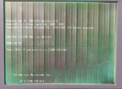
It turned out to be the RAM. A friend with a desoldering station removed the RAM chips for me and I replaced them with sockets. Then I tried the same chips in the sockets, shuffling them around a bit. I'm guessing that the centre one (U2) is probably parity, and certain chips in that position cause the error (1 very long beep and 3 short bips). But with others, there was the usual POST beep and my test machine seemed to be booting, albeit with a blank display.
So I tried the switch utility and shift-control-D... and was completely blown away to have a completely normal screen appear. Holy moly, it works! 😁

I used the same switch settings as Jonas-fr (again, thanks!)... Interestingly, I had no artifacts or garbled display in any mode that I tested: CGA, EGA, VGA 320x200, VGA 640x480, and 80x25 text. That's not necessarily a conclusive RAM test of course, but I'm wondering if the RAM is "mostly" ok, but just fails whatever test the card BIOS is using. I've ordered some new 41464 chips anyway.

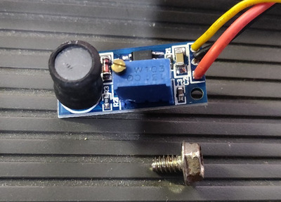
The next step is to create a -22V supply for testing the LCD panel itself, since the original PSU from the portable is dead.

Long journey... sorry for the necropost, but maybe this will help someone else too.

Thanks again! 😀

It don't mean a thing if it ain't got 5-pin DIN.
Roland addict and founding member of the Association Of Molex Haters

Reply 26 of 30, by matze79

User metadata
Rank l33t
Rank
l33t

Ah shit forgot the dump, Sorry!

https://www.retrokits.de - blog, retro projects, hdd clicker, diy soundcards etc
https://www.retroianer.de - german retro computer board

Reply 27 of 30, by PD2JK

User metadata
Rank Oldbie
Rank
Oldbie

Nice read, congratulations. 😀

i386 16 ⇒ i486 DX4 100 ⇒ Pentium MMX 200 ⇒ Athlon Orion 700 | TB 1000 ⇒ AthlonXP 1700+ ⇒ Opteron 165 ⇒ Dual Opteron 856

Reply 28 of 30, by InbetweenDays

User metadata
Rank Newbie
Rank
Newbie
incanus wrote on 2021-02-01, 18:44:

Awesome, really glad to hear it @InbetweenDays! I'm curious how your recreation of the -22V PSU goes as that's a weak point of my setup (or any of these) as far as bizarre, unique parts goes.

Easy done... grab yourself one of these from eBay: "MC34063A Reverse Voltage Module Positive To Negative Voltage Converter". I just got mine today and it works perfectly to get the -22V
So now my LCD is, well, let's say operational at least. Pics below... anyone know if this is fixable? I guess it works well enough to see what I'm doing to switch to an external display... 😒

By the way the module is a lot smaller than I expected - pictured here on top of the portable, next to a standard #6-32 UNC case screw.

IMG_20210212_142250.jpg
Filename
IMG_20210212_142250.jpg
File size
104.46 KiB
Views
1060 views
File license
Public domain
IMG_20210212_142207.jpg
Filename
IMG_20210212_142207.jpg
File size
88.26 KiB
Views
1060 views
File license
Public domain
IMG_20210212_142156.jpg
Filename
IMG_20210212_142156.jpg
File size
95.47 KiB
Views
1060 views
File license
Public domain

It don't mean a thing if it ain't got 5-pin DIN.
Roland addict and founding member of the Association Of Molex Haters

Reply 29 of 30, by Ozzuneoj

User metadata
Rank l33t
Rank
l33t
InbetweenDays wrote on 2021-02-12, 06:30:
Easy done... grab yourself one of these from eBay: "MC34063A Reverse Voltage Module Positive To Negative Voltage Converter". I j […]
Show full quote
incanus wrote on 2021-02-01, 18:44:

Awesome, really glad to hear it @InbetweenDays! I'm curious how your recreation of the -22V PSU goes as that's a weak point of my setup (or any of these) as far as bizarre, unique parts goes.

Easy done... grab yourself one of these from eBay: "MC34063A Reverse Voltage Module Positive To Negative Voltage Converter". I just got mine today and it works perfectly to get the -22V
So now my LCD is, well, let's say operational at least. Pics below... anyone know if this is fixable? I guess it works well enough to see what I'm doing to switch to an external display... 😒

By the way the module is a lot smaller than I expected - pictured here on top of the portable, next to a standard #6-32 UNC case screw.

IMG_20210212_142250.jpg
IMG_20210212_142207.jpgIMG_20210212_142156.jpg

This has really come along nicely! Great job!

As for the visual corruption, I'd use my super scientific method: Poke every video related component or connection with something non-conductive to check for any bad physical connections or broken solder joints. I have had video cards clearly respond to physical prodding while they were displaying artifacts\lines on the screen. This can take some of guess work out of the diagnoses. Though if you see the corruption getting worse and worse, it may be best to not power it on again. Also, if there are any jumpers involved, make sure they are tight and not oxidized. Lastly, it could be capacitor related, but without seeing the LCD components it's hard to say.

Now for some blitting from the back buffer.

Reply 30 of 30, by InbetweenDays

User metadata
Rank Newbie
Rank
Newbie

The new RAM chips fixed the corruption - well, the vertical lines at least. It's interesting that the dodgy ones work fine with an external display, with no visible artifacts.
The only thing left is that dark horizontal line through the middle of the LCD, which I'm assuming to be a problem with the panel itself. I'll eventually rip it open and see if I can clean any contacts etc.

It don't mean a thing if it ain't got 5-pin DIN.
Roland addict and founding member of the Association Of Molex Haters