VOGONS


First post, by SSTV2

User metadata
Rank Oldbie
Rank
Oldbie

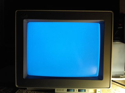
Long story short as possible. Had a dead IBM 8518 monitor in an attic for over 10 years, which had a shorted HOT, fixed the thing by replacing it with better characteristics transistor, tested surrounding components that could've caused previous HOT to blow, found nothing, tested monitor and put it back in a working order where it came from. Brought it back after a few months to mate it with a IBM PS/2 Model 8590 and the thing blew again (can't remember how long it lasted). Thought that HOT was shot again and w/o second thought put it back, as it was obvious that w/o extensive fault checking, monitor won't stop blowing HOTs.

5~ years later I've decided to finish it once and for all.

After checking the whole horizontal deflection output circuit, I was slightly surprised, because nothing went bad there and HOT was infact OK. It was the horizontal centering circuit that suffered damage (two low power BJTs and a 4.7R resistor). Now I have no idea why did that happen as no component in that area was faulty or off specs...

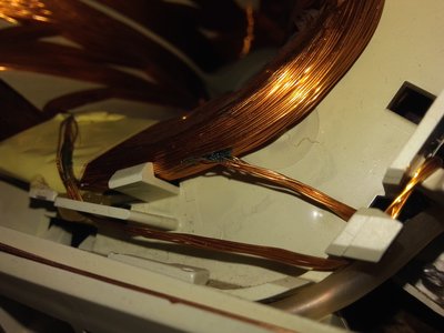
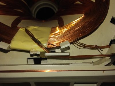
Now I'm suspecting a LOPT/flyback transformer, but w/o schematics I cannot be 100% sure how secondary coils should be wired, hence I'm looking for any of the listed monitors schematics, as all of those models use a compatible LOPT. Made myself a Dick Smith LOPT/FBT tester just to test it, the primary winding is OK (all 8 leds light up) but pins 6 and 7 (responsible for horizontal centering) are shorted together + with B+ line pin on the primary winding.

w2.jpg
Filename
w2.jpg
File size
1.98 MiB
Views
1153 views
File license
Fair use/fair dealing exception

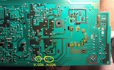
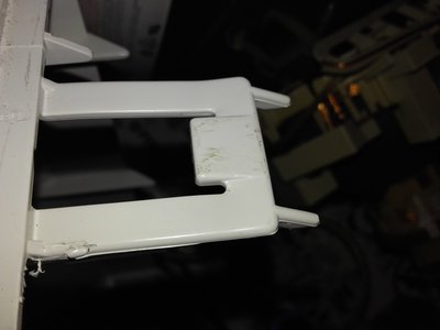
Pins 1,2 - primary winding, pins 3,4 - NC, on pins 5,9,10 LOPT tester shows a short, pins 2,3,6,7 - short, but neither shorts with pin 1 (LOPT part number - FTS-14A005 or FTS-14A007 samsung). Areas marked in red, had completely dead components.

If anyone has service manual for any of the mentioned monitors in the description, please upload schematic of LOPT section here.

Reply 1 of 17, by SSTV2

User metadata
Rank Oldbie
Rank
Oldbie

Reassembled mainboard and turned on a monitor, heard arcing noise from deflection coils and instantly powered it down. Disconnected horizontal deflection coil and arcing stopped, but there was no heater voltage present on the neckboard (thus no vertical white line) though G1, G2, RGB voltages were present. Tested heater filaments, no open or short there, I know for sure that heater voltage should be present, regardless deflection coils are connected or not, strange... Heater voltage comes from LOPT 9th pin, current path to fillaments is OK, no open resistors etc. I think that HV might have also been absent.

Charred windings at the very beginning of the coil, though no dead short, LOPT tester wouldn't detect such failure.

1.jpg
Filename
1.jpg
File size
1.58 MiB
Views
1113 views
File license
Fair use/fair dealing exception
2.jpg
Filename
2.jpg
File size
1.72 MiB
Views
1113 views
File license
Fair use/fair dealing exception

Gradual horizontal coil failure most likely caused original HOT to blow.

Reply 3 of 17, by SSTV2

User metadata
Rank Oldbie
Rank
Oldbie

Uploading pictures of plastic latches for future reference, it can be pain in the arse to remove back cover when you don't know how these latches work.

i.jpg
Filename
i.jpg
File size
1.34 MiB
Views
1061 views
File license
Fair use/fair dealing exception
o.jpg
Filename
o.jpg
File size
1.02 MiB
Views
1061 views
File license
Fair use/fair dealing exception

And of course:

s.jpg
Filename
s.jpg
File size
1.43 MiB
Views
1061 views
File license
Fair use/fair dealing exception

Reply 4 of 17, by devius

User metadata
Rank Oldbie
Rank
Oldbie

Hey, I just started trying to repair a non-working IBM 8518 and the pictures of the plastic latches were very helpful. I'm also curious about what was the fix in the end in your case. Can you explain what was the problem and how you fixed it?

Reply 5 of 17, by SSTV2

User metadata
Rank Oldbie
Rank
Oldbie

Hello, both times the circuit failure was caused by a bad horizontal deflection coil. The first time I replaced only the horizontal output transistor, the second time there were more minor faults like open resistors and shorted low power BJTs in the horizontal centering circuit, and somehow a XOR chip responsible for H / V synchronization managed to fry itself.

Reply 8 of 17, by devius

User metadata
Rank Oldbie
Rank
Oldbie

I suspect there's some short circuit somewhere that causes the monitor to not even start up, since when I plug it in and turn it on the power LED doesn't even turn on. I suspect there's no high voltage at all since all the usual CRT start up sounds are missing, and the only sound I hear is a repeating "beep" like sound, that seems just like some over-voltage or over-current protection kicking in.

Reply 9 of 17, by SSTV2

User metadata
Rank Oldbie
Rank
Oldbie

I had an exact symptom the 1st time, power was cycling and you could hear a chirping noise coming from the PSU, though LED light was also cycling in my case, you might have a short somewhere in one of the PSUs rails, check which rail powers the LED.

Reply 10 of 17, by pentiumspeed

User metadata
Rank l33t
Rank
l33t

Fixed my 8518 monitor back then, all it had was main capacitor that bloated.

Much better monitor than 8513 which I knew well were high failure rate and poorly designed.

Cheers,

Great Northern aka Canada.

Reply 11 of 17, by devius

User metadata
Rank Oldbie
Rank
Oldbie

Fixed!

IMG_20220508_125824.jpg
Filename
IMG_20220508_125824.jpg
File size
244.91 KiB
Views
682 views
File comment
Fixed IBM 8518 monitor
File license
GPL-2.0-or-later

The only problem was a shorted horizontal output transistor as well. Also re-soldered what seemed like a cold solder joint on a capacitor near the failed transistor for good measure. I hope the root cause isn't a bad deflection coil. SSTV2, is there a way to test this hypothesis?

Reply 12 of 17, by SSTV2

User metadata
Rank Oldbie
Rank
Oldbie

Great job!

Was that capacitor with a cold solder joint connected between ground and the HOT collector? If so, it means that the transistor has shorted out because a snubber (or safety) capacitor was lost. The purpose of that capacitor, together with a damper diode, is to protect the HOT from a high inrush current/voltage spike during retrace period, when the magnetic field in the primary winding of a flyback TR colapses.

Once I tried to adjust the horizontal width of one monitor by trying different capacitance snubber caps and accidentally turned monitor on without one in place, needless to say, HOT shorted out immediately.

Reply 13 of 17, by devius

User metadata
Rank Oldbie
Rank
Oldbie

That's exactly it! It was the big 1600V film cap. Well, that's one mystery solved. Thanks for all your help! Now I need to clean this thing to make it look more presentable.

Reply 15 of 17, by devius

User metadata
Rank Oldbie
Rank
Oldbie

So, I may not have been that lucky after all. When I had it open everything was fine, and even after I put it back and cleaned all the plastics it was still working fine apparently, but then I noticed that if I gave it a nudge the image would briefly flash brighter and with horizontal and diagonal lines which wasn't a good sign.

I think there may be another cracked solder joint somewhere since the bright image now just comes and goes randomly but tapping the monitor definitely either fixes it or causes it temporarily. Any ideas where I should look for before I take it apart again?

IMG_20220514_153906.jpg
Filename
IMG_20220514_153906.jpg
File size
276.25 KiB
Views
628 views
File comment
Image too bright
File license
GPL-2.0-or-later

Reply 16 of 17, by SSTV2

User metadata
Rank Oldbie
Rank
Oldbie

Try reseating CRT's neckboard in the first place, if it doesn't solve the problem then sligtly tap or turn "screen" adjustment pot on the flyback transformer, if that doesn't help either, inspect brightness and contrast adjustment circuitry for cold solder joints, neckboard or area around flyback. Make sure that the flyback transformer is properly soldered.

Reply 17 of 17, by devius

User metadata
Rank Oldbie
Rank
Oldbie

Alright, I think those tips helped. I didn't end up needing to check the flyback transformer since just securing the neckboard better helped. I noticed that one of the metal stand-offs that attaches the metal shield to the neckboard wasn't attached at all, so I attached it and that made a big difference. The image is stable now when adjusting the tilt, swivel and when lightly tapping on the screen.

Here it is in all its glory:

IMG_20220516_222358.jpg
Filename
IMG_20220516_222358.jpg
File size
186.02 KiB
Views
595 views
File comment
IBM PS/2 Model 30 286 + IBM 8518 monitor
File license
GPL-2.0-or-later