VOGONS


First post, by GigAHerZ

User metadata
Rank Oldbie
Rank
Oldbie

Hi guys.

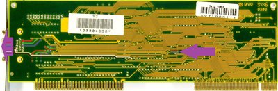
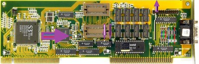
I have an S3 86C805-P VLB graphics card, which has very dim picture and the lcd screen struggles to properly auto adjust to it. In the same machine, other vga cards work great.

The card is like that: http://www.vgamuseum.info/images/palcal/s3/34 … .C.J_top_hq.jpg
(I have exactly the same kind of card)

What could cause it? Should i recap the electrolytics? (there's 4 of them)

Thanks!

"640K ought to be enough for anybody." - And i intend to get every last bit out of it even after loading every damn driver!

Reply 1 of 22, by GigAHerZ

User metadata
Rank Oldbie
Rank
Oldbie

Update: I did the recapping, but it didn't change the signal quality.
Any ideas?

"640K ought to be enough for anybody." - And i intend to get every last bit out of it even after loading every damn driver!

Reply 2 of 22, by Tiido

User metadata
Rank l33t
Rank
l33t

See if the RAMDAC is getting power and the support components are all there. Chances are the RAMDAC is damaged.

T-04YBSC, a new YMF71x based sound card & Official VOGONS thread about it
Newly made 4MB 60ns 30pin SIMMs ~
mida sa loed ? nagunii aru ei saa 😜

Reply 3 of 22, by appiah4

User metadata
Rank l33t++
Rank
l33t++

If the signal is low on all colour channels then that points to a possible problem all the way back at the source, so either the chipset or probably RAMDAC is damaged as Tiido pointed out..

Retronautics: A digital gallery of my retro computers, hardware and projects.

Reply 4 of 22, by Doornkaat

User metadata
Rank l33t
Rank
l33t

Check the signal path of RGB and H/VSync from the RAMDAC/buffer to the VGA connector. Is there continuity? High resistance where there shouldn't be any? Are the diodes ok? Are the resistors near the VGA connector ok? (And do they connect to ground btw? Anyone know what's up there?)
If all checks out it's most likely the RAMDAC as already explained.

Attachments

Reply 5 of 22, by GigAHerZ

User metadata
Rank Oldbie
Rank
Oldbie

@Doornkaat, thank you for those pics! At last i got back to this thing now...
All looks good with multimeter.

At the same time, on second picture, near the D-SUB connector, there are 6 diodes right? Should they give a beep as well with multimeter? Right now, on both directions, with bottom 3 diodes i get ~70 ohms, and on top diodes i get overload both directions. (Testing with the beep mode of multimeter)

Is that normal? What should i see on those diodes?

"640K ought to be enough for anybody." - And i intend to get every last bit out of it even after loading every damn driver!

Reply 6 of 22, by chrismeyer6

User metadata
Rank l33t
Rank
l33t

Normally with a diode you should get continuity in one direction and nothing on the reverse direction. The diodes where you get no continuity is that in both directions?

Reply 8 of 22, by ATauenis

User metadata
Rank Member
Rank
Member

S3 cards are frequently have dark and dim picture. And this is not a damage. The only way to fix it is to use a good CRT screen and set 100% brightness/contrast.

Also it's a cheat to play Quake/Q2/HL easier on all cards. 😀

2×Soviet ZX-Speccy, 1×MacIIsi, 1×086, 1×286, 2×386DX, 1×386SX, 2×486, 1×P54C, 7×P55C, 6×Slot1, 4×S370, 1×SlotA, 2×S462, ∞×Modern.

Reply 10 of 22, by GigAHerZ

User metadata
Rank Oldbie
Rank
Oldbie

@chrismeyer6, i get no continuity in any direction with any diode...

"640K ought to be enough for anybody." - And i intend to get every last bit out of it even after loading every damn driver!

Reply 12 of 22, by maxtherabbit

User metadata
Rank l33t
Rank
l33t
chrismeyer6 wrote on 2020-01-26, 14:39:

I'd still replace them as you should get continuity in one direction and nothing in the opposite direction.

with a standard continuity test diodes will not show continuity in either direction, that is normal

the continuity test fails in the forward direction due to the intrinsic voltage drop through a diode, you need to use the diode test mode

Reply 13 of 22, by GigAHerZ

User metadata
Rank Oldbie
Rank
Oldbie
maxtherabbit wrote on 2020-01-26, 15:51:
chrismeyer6 wrote on 2020-01-26, 14:39:

I'd still replace them as you should get continuity in one direction and nothing in the opposite direction.

with a standard continuity test diodes will not show continuity in either direction, that is normal

the continuity test fails in the forward direction due to the intrinsic voltage drop through a diode, you need to use the diode test mode

Okay, diode testing mode shows volts, therefore it's a voltage drop right?

Bottom 3 diodes: Both directions, always 0.04V.
Top 3 diodes: one way 0.35V, other way 0.66V.

Are those six things even diodes? By my limited knowledge, diodes should not behave like that, right?

"640K ought to be enough for anybody." - And i intend to get every last bit out of it even after loading every damn driver!

Reply 14 of 22, by maxtherabbit

User metadata
Rank l33t
Rank
l33t

they should be diodes yes, specifically protection diodes

the top three should be oriented with the anode toward ground and the cathode toward the DAC color outputs - this protects the DAC from a negative potential being applied to the color lines from an external source by allowing (conventional) current to flow from ground to R, G, B

bottom three *should* be doing the inverse, anode toward R, G, B cathode toward +5 to protect the DAC from positive potential. I can't see anything connected to the southern vias of the bottom diodes to confirm this though.

you should be able to remove all 6 of them and still use the output for testing purposes

Reply 15 of 22, by gdjacobs

User metadata
Rank l33t++
Rank
l33t++
GigAHerZ wrote on 2020-01-26, 15:57:

Bottom 3 diodes: Both directions, always 0.04V.

Failed short?

All hail the Great Capacitor Brand Finder

Reply 16 of 22, by appiah4

User metadata
Rank l33t++
Rank
l33t++

0.04V on either direction sounds suspicious but a failed short should give 0V? Could be an issue with multimeter's accuracy too..

Retronautics: A digital gallery of my retro computers, hardware and projects.

Reply 17 of 22, by gdjacobs

User metadata
Rank l33t++
Rank
l33t++
appiah4 wrote on 2020-01-27, 12:04:

0.04V on either direction sounds suspicious but a failed short should give 0V? Could be an issue with multimeter's accuracy too..

Yeah, 0.04V is pretty much equivalent to 0.00V except in very low power measurements. It's in the range of a typical forward measurement on a diode.

All hail the Great Capacitor Brand Finder

Reply 18 of 22, by GigAHerZ

User metadata
Rank Oldbie
Rank
Oldbie

@appiah4, @gdjacobs, i'm quite sure, multimeter is fine in general. I think only thing we care is that i measured same voltage drop on both directions, right?

Looks like those diodes should be replaced, right?
Any ideas, what kind of diodes should i order? Can't really read anything readable out from them...

"640K ought to be enough for anybody." - And i intend to get every last bit out of it even after loading every damn driver!

Reply 19 of 22, by Tiido

User metadata
Rank l33t
Rank
l33t

Those are standard 1N4148 type things. Any high-speed signal diode will do and you can even get away by not having any at all, especially for testing. Remove them and if the problem presists you know the RAMDAC or its support components have a problem instead.

T-04YBSC, a new YMF71x based sound card & Official VOGONS thread about it
Newly made 4MB 60ns 30pin SIMMs ~
mida sa loed ? nagunii aru ei saa 😜