Well, I have good news and not-so-good news.
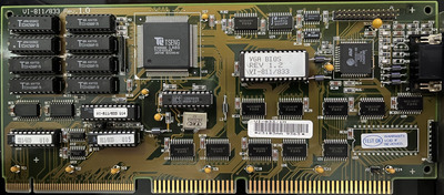
The good news is that the video card is probably fine. First of all, mkarcher you were absolutely right regarding how the data lines are handled. With a multimeter and some patience, I traced all 32 data lines from the ET4000AX chip to the F245 chips and finally to the ECS Local Bus (let's call it ELB) connector: U25/U18 handle D0-D7/D16-D23 while U30/U19 handle D8-D15/D24-D31. All connections were good, so if there was any problem with the card it would be U30.
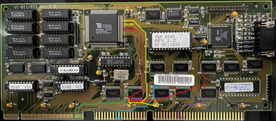
To confirm these findings and discard issues on the motherboard side, I decided to trace the connections of the data lines from the ELB slot to the 486 CPU socket. And all of them connected directly, just as expected... except for one: D8. There was no continuity between the CPU F-2 pin (D8) to B17 in the ELB slot (which is the pin connected to U30-B0 on the card). So, this is likely the cause of the problem, and again mkarcher you were correct about discarding issues on the motherboard side 😃.
Now, I could have just run a bodge wire between the two pins and called it a day, but I wanted to see exactly where the problem was and try to fix it in a more elegant way. First I tried reflowing the pins on both the CPU socket and the ELB slot, but no change. Then I checked continuity from the D8 pin of the CPU to the 487 socket, and they were connected, so I concluded that the pin and its via were probably OK, no cracked solder joint or anything that would otherwise have isolated it.
So turned my attention to the ELB slot, and noticed there were no traces coming from the B17 pin on the underside, so it had to be on the top side, right? Well, the problem is that the slot itself and a large amount of components were blocking my view. I then decided to desolder the slot and see what was going on there. Luckily, it came out quite cleanly, no torn pads or other damage... but I was disappointed to see that there was no trace on the top side either! Looks like B17 (and a few other data lines) are routed from the slot to the CPU in one of the internal layers! And it looks like the one that connects the D8 line broke at some point.
I've heard stories about boards with VLB or similar long slots would break traces in the inner layers due to the motherboard bending because of the force needed to insert the cards, but it had never happened to me before. Being honest, I only inserted the card a few times and I always make sure the board is properly supported so it doesn't bend. Maybe the trace was already marginal when I got the board from its previous user, so who knows?
In any case, looks like a bodge wire is the only solution (after I resolder the slot), but I am concerned about a couple of things:
- Do I have to keep the wire length limited, considering the board runs at 50MHz FSB? I'm wondering about any possible electrical limitations at that frequency
- Hopefully it's just the trace from the slot to the CPU that broke, and that it doesn't need to go somewhere else (such as a termination resistor or something)