VOGONS


First post, by clb

User metadata
Rank Member
Rank
Member

While testing out different ISA VGA cards, I find that some cards have a really peculiar video mode 0Ah in their BIOS, which produces a seemingly broken crazy high 178 Hz refresh rate video mode.

At first I thought that this was just some quirk of one VGA card, but now in my tests, I am seeing that several graphics cards from different manufacturers produce this same video mode when activating mode 0Ah via INT 10h. These include:
- WD90C30-LR, pictured in (ViewTOP) WD90C30-LR ISA VGA DIP switches: play DOS games at 90hz refresh rate
- CL-GD5422,
- Nokia/Paradise PVGA1A-JK,
- Everex Viewpoint EV628/AVGA1
- Ahead V5000

and maybe others. The following cards have been tested NOT to have this video mode:
- Trident 8900C and 8900D,
- CL-GD5428,
- Diamond SpeedStar 24 (Tseng ET4000AX),
- Oak OTI037C,
- Video 7 VGA 1024i/Headland HT208

This mode has the following parameters, as measured from WD90C30-LR:

Pixel clock: 25.257799 MHz,
Hsync: 46.774 kHz,
Vsync: 178.526 Hz,
Horizontal total: 540 pixels,
Vertical total: 262 lines,
Active screen size: 198x246 pixels
Horizontal: 4 px front porch, 36 px hsync, 302 px back porch
Vertical: 1 line front porch, 3 lines vsync, 12 lines back porch

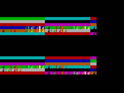
When I fill the video memory in segments A000h-AFFFh and B000h-BFFFh with increasing bytes (e.g. memory index i in the segment gets byte value i), I get this mode to produce the following kind of video output, as shown in the attached screenshot. However what is strange about this is that I need to do the video memory fill *before* entering this mode, or otherwise the writes will not show up on screen.

In other words, if I first enter the video mode 0Ah, then fill up both segments A000h and B000h with test bits, the screen will end up staying blank. But if I first enter video mode 07h, then do the fill, then the image pattern will show up.

All this makes me think this is that this is some kind of "broken" mode to some effect. Although what makes me still ponder about this, is that:
a) multiple cards have this exact same behavior, as if it was intentional design somehow, and
b) these cards I have tested generally don't seem to have many broken video mode ID numbers, most ID numbers that are not associated with a mode, will generally fail to set anything, and querying the current active video mode will not change. But not in this case.

This mode is some kind of 16 colors text mode, some of the "characters" have the blink bit on.

Searching for this mode 0Ah on the web, I only find mentions about a 640x200 PCjr/Tandy video mode in that mode number slot, but this is definitely not it.

On the WD90C30-LR card from this thread, this mode changes to a hilarious 224 Hz vsync, 58.6 kHz hsync rate when DIP5 is set to be enabled. I can't recall what exactly caused the most strain on old CRTs, but this could be quite the CRT monitor torturer for anyone who dislikes CRTs.

Anyone has any clues? 😀

Attachments

  • mode_0Ah.jpg
    Filename
    mode_0Ah.jpg
    File size
    123.23 KiB
    Views
    870 views
    File license
    Public domain

Reply 1 of 9, by VileR

User metadata
Rank l33t
Rank
l33t

I seem to recall that some VGA references listed video modes in the range 08h-0Ch as "reserved for internal video BIOS operation". Or something along those lines, implying that they technically have some functionality but aren't supposed to ever be specified by user code.

These might be good pointers towards a clue:

- When executing INT 10h function 1Bh (Get Functionality/State Information), see if the Static Functionality Table indicates mode 0Ah as available ( = byte 1, bit 2)
- See if the VGA BIOS's Video Parameter Table has anything for mode 0Ah

Had a quick look at one CL-GD5422 VBIOS; it appears to state that mode 0Ah is not supported - but apparently this is not checked when setting the video mode, because setting mode 0Ah does result in a strange garbled 177.94Hz text mode.
The Video Parameter Table *does* have an entry for mode 0Ah. See the format for the meaning of the different values, which probably explains the funny timing parameters you get.

00000280h: 28 18 08 00 40 00 00 00 03 23 37 27 2D 37 31 15 ; (...@....#7'-71.
00000290h: 04 11 00 47 06 07 00 00 00 00 E1 04 C7 14 08 E0 ; ...G......á.Ç..à
000002a0h: F0 A3 FF 00 01 02 03 04 05 06 07 10 11 12 13 14 ; ð£ÿ.............
000002b0h: 15 16 17 08 00 0F 00 00 00 00 00 00 10 0E 00 FF ; ...............ÿ

...then again, I can set video mode 0Bh too, which apparently is something like 35Hz (and completely blank output). So 0Ah probably isn't unique in that regard.

[ WEB ] - [ BLOG ] - [ TUBE ] - [ CODE ]

Reply 2 of 9, by VileR

User metadata
Rank l33t
Rank
l33t

Ah, there you go: the original IBM VGA BIOS also has parameters for mode 0Ah in its VPT, almost (but not quite) identical to the Cirrus Logic BIOS above. The only difference is in offset 1Bh, in the apparently unused(?) bit 5 of CRTC register 11h.

00000280h: 28 18 08 00 40 00 00 00 03 23 37 27 2D 37 31 15 ; (...@....#7'-71.
00000290h: 04 11 00 47 06 07 00 00 00 00 E1 24 C7 14 08 E0 ; ...G......á$Ç..à
000002a0h: F0 A3 FF 00 01 02 03 04 05 06 07 10 11 12 13 14 ; ð£ÿ.............
000002b0h: 15 16 17 08 00 0F 00 00 00 00 00 00 10 0E 00 FF ; ...............ÿ

Its presence in the IBM VGA BIOS probably explains why quite a few others have it too; modes 0Bh and 0Ch also have their own entries. This may even go back to the EGA (haven't checked). Still doesn't explain what "internal operation" it's actually supposed to accomplish...

[ WEB ] - [ BLOG ] - [ TUBE ] - [ CODE ]

Reply 3 of 9, by clb

User metadata
Rank Member
Rank
Member

Hey, thank you so much for investigating this, that was super informative. I meant to do a "quick followup" to write test code that would test the INT 10h function 1Bh and get back to this, but then days dragged on and soon turned to weeks.. so took a bit of delay here..

I was now able to write that test code, and now see the functionality table is indeed there for these cards. Strangely, I see that an ATI PCI video card also has those same modes, but the VGA static functionality table never advertises these.

I tried for a bit to program these modes to see if I could do something remotely useful with them, but looks like the memory mapping from these modes does not make much sense, so nothing can really be gained that could not be done by directly programming the VGA registers (well, like one would expect since the modes are already "just" presets to the register states anyways)

Your hypothesis is probably spot on that manufacturers copied that functionality table to their implementations to be fully compatible, without even wondering what it means.

Thanks also for pointing out that INT 10h function 1Bh, I was not aware of that function from before. Took a bit of time to dump the info I get from that. I was curious if I could enumerate supported VGA video modes with this function, similar to how VESA video mode enumeration works. But looks like the fields are not quite as robust or forward proof so that different manufacturers would have been able to advertise the custom non-VESA SVGA video modes that they support via these information tables. Oh well...

Reply 4 of 9, by mkarcher

User metadata
Rank l33t
Rank
l33t

Common folklore has it that modes 0B / 0C are used for text mode font upload. It's not surprising you can not write to video memory in this mode, because the write mask regsiter (SEQ index 2) is set to zero, masking all writes. 262 active lines sound a lot like standard CGA NTSC timing, but you would need a 8.478 MHz dot clock to get 15.7kHz horizontal frequency at a horizontal total of 540 pixels, which is not available on any video card I know. If that mode was targeted for the EGA CRTC, the horizontal total wouldn't be 60 character clocks, but just 57 character clocks. If, again, the character width wouldn't be 9 pixels, but just 8 pixels, this would mean a horizontal total of 456 pixels. 15.7kHz * 456 pixels results in a pixel clock of 7.16MHz, which is exactly half of the CGA-compatible pixel clock available on the EGA card. So I'd expect this mode originated from some internal use on the original EGA BIOS, in which it was intended to hit the standard NTSC timing, and has been left bit-rotting since then.

Reply 5 of 9, by clb

User metadata
Rank Member
Rank
Member

Yeah, quite plausible.

Sidenote, looking at the state info register at http://www.ctyme.com/intr/rb-0221.htm , I find that it is possible to query the current video mode for how many text rows and columns it has, and how many colors they each have. I wonder if there might be a way to query what the pixel width & pixel height of a single text character is in the current video mode? That would enable calculating the pixel size of the currently set VGA video mode.

Also I wonder if there is a way to know if the current video mode is a graphics or a text mode? I think with that info, maybe it would be possible to loop through 0x00 ... 0x7F to probe what kind of video modes each of those VGA BIOS extended modes would then produce. What I am thinking of is building a similar kind of enumeration function for VGA BIOS video modes, like the VESA mode enumeration is.

Reply 6 of 9, by akallio

User metadata
Rank Newbie
Rank
Newbie

My copy of Ralf Brown's interrupt list (Copyright (c) 1989-1999,2000 Ralf Brown) lists 0Ah as a valid 640 x 200 4 color video mode for the PC Jr. and Tandy 1000, and as a 132 x 25 text mode for some Everex video cards.

Reply 7 of 9, by mkarcher

User metadata
Rank l33t
Rank
l33t
clb wrote on 2023-07-22, 20:49:

Sidenote, looking at the state info register at http://www.ctyme.com/intr/rb-0221.htm , I find that it is possible to query the current video mode for how many text rows and columns it has, and how many colors they each have. I wonder if there might be a way to query what the pixel width & pixel height of a single text character is in the current video mode? That would enable calculating the pixel size of the currently set VGA video mode.

Also I wonder if there is a way to know if the current video mode is a graphics or a text mode? I think with that info, maybe it would be possible to loop through 0x00 ... 0x7F to probe what kind of video modes each of those VGA BIOS extended modes would then produce. What I am thinking of is building a similar kind of enumeration function for VGA BIOS video modes, like the VESA mode enumeration is.

If you are hunting for legitimate SVGA modes, this might work, although it was common to not implement proper BIOS support for high-color and true-color modes. There are notable differences between text and graphics modes:

  • The PutPixel/GetPixel functions only work in graphics mode. So putting color 0 to pixel 0,0 and reading it back, then putting color 1 to that pixel and reading it back should return 0 and 1 respectively only in graphics mode. Make sure you write a value different from 0 or 1 into the output register before you call GetPixel.
  • The TTY write function in text modes writes in the "current color" (either the color already present at that location, or the color of the top left character), but in graphics mode it takes the color to use in a caller-specified register. IIRC the read character function returns the color of a character if it managed to recognize a character.
  • The read character function in graphics mode does pixel-perfect character matching. If it doesn't find any match, it returns 00 or FF. The standard graphics font has three characters with identical pixel layout: 00, 20 and FF (all of them being completely blank). Writing these three distinct character codes using "write character and attribute" or "TTY write", and then reading them back with "read character" will return thrice the same value in graphics mode, and three different character codes in text mode

I don't see how you have a chance of automatically detecting whether you are operating at a 8-pixel or 9-pixel character box in text mode. You would need to fetch that information from the hardware. As this is a standard EGA/VGA feature, fetching this bit is likely returning valid data even in SVGA text modes.

But, as I wrote in the introduction, this applies to officially supported modes. Modes that are considered "invalid" might still be settable using INT 10h, AH=0 (that's the point of this thread), but they do not need to behave consistently. For example, the mode 0A data quoted by VileR begin with "28 18", which indicates a 40 x 25 character text capacity. This is what will be returned by the BIOS mode information functions. The CRTC programming is contained in different registers, though, and might differ. In the BIOS dumps quoted by VileR, the horizontal display end register contains 27 hex (which is 39), which indicates that the CRTC is indeed set up to display 40 characters. The programmable overscan color is displayed for 5 characters at the right border, as well as 5 characters at the left border (interpreting horizontal total as a VGA CRTC would do), which is a non-blank picture width of 50 characters, i.e. 400 pixels on a 8-pixel character box and 450 pixels on 9-pixel character box. The character box width is set by the SEQ register 1, lowest bit. As this bit is clear, we are getting a 9-pixel character box indeed. So the dumps contain a mode with 360 pixels producing image data and 90 extra colored overscan pixels for a total active width of 450 pixels.

The data quoted by cbd in the first post suggesting 192 active pixel might be based on a misunderstanding, or the WD card the timings were taken from uses a slightly different parameter set. I don't see how cbd's measured timings can be produced by standard VGA hardware, because the dispayed image width, the border width, the front and back porch and the sync width are supposed to be an integer number of characters, so they are supposed to be a multiple of 8 or 9 pixels. The measurement data don't agree with it. Maybe some invalid configuration (like blanking start before display end) cause a VGA card to generate unexpected timings, and the measurements are indeed correct. If the measurements are correct and caused by an inconsistent set of CRTC parameters, I highly doubt that the mode data returned by the BIOS about this mode are correct.

A final note about high-color / true-color modes: The ARK BIOSes I'm currently looking at report twice as much characters than there really are in high-color modes, and thrice as much in true-color modes (24bpp true color), clamping the character count to 255 if it would exceed the maximum value representable in a byte (like in 800x600 true color, which has 100 real characters, i.e. 300 fake characters).

Reply 8 of 9, by VileR

User metadata
Rank l33t
Rank
l33t
mkarcher wrote on 2023-07-22, 20:26:

If that mode was targeted for the EGA CRTC, the horizontal total wouldn't be 60 character clocks, but just 57 character clocks. If, again, the character width wouldn't be 9 pixels, but just 8 pixels, this would mean a horizontal total of 456 pixels. 15.7kHz * 456 pixels results in a pixel clock of 7.16MHz, which is exactly half of the CGA-compatible pixel clock available on the EGA card. So I'd expect this mode originated from some internal use on the original EGA BIOS, in which it was intended to hit the standard NTSC timing, and has been left bit-rotting since then.

Interesting observation. Unsurprisingly, the parameters for modes 08h through 0Ah also exist in IBM's EGA BIOS, and at least mode 0Ah has the same parameters we see in the IBM VGA (haven't compared the others yet). Except that the VGA changes CRTC register 9 from 07h to 47h - i.e. it sets bit 9 of the Line Compare value to 1. I believe that bit was only introduced with the VGA, so if someone at IBM bothered to change it, perhaps there was still some obscure use for that mode after all?

But yes, on the EGA it works out to 57 characters/456 pixels per scanline, which is exactly what CGA uses in all modes except for 80-column text. In fact EGA modes 8, 9, A have the same horizontal timings as the 200-line ("EGA-on-CGA") versions of modes 0 and 1, which already have the standard 15.7kHz NTSC timing... or as close to the standard as CGA itself was.

Maybe at some point they were going to include CGA-like composite output. The EGA BIOS listing has an outdated reference to "color burst" and "BW modes", which only ever had an effect on CGA, and only on the composite output.

Problem is, modes 8,9,A also set sequencer register 1 to 00 - i.e. they use the 9-dot clock, and don't even divide it by 2; so the pixel clock is the same as mode 7 (MDA-like). With the CGA-like CRTC timings, you'll obviously get complete nonsense.
(Not to mention that all plane writes are masked out, as you noted; so even if you got a stable picture somehow, you couldn't make it all that interesting to look at.) 😀

[ WEB ] - [ BLOG ] - [ TUBE ] - [ CODE ]

Reply 9 of 9, by mkarcher

User metadata
Rank l33t
Rank
l33t
VileR wrote on 2023-07-23, 19:12:

Problem is, modes 8,9,A also set sequencer register 1 to 00 - i.e. they use the 9-dot clock, and don't even divide it by 2; so the pixel clock is the same as mode 7 (MDA-like).

It's correct what you observe about register sequence register 1: character clock is pixel clock divided by 9, and pixel clock is master clock. To get 40-character CGA timing, you would neet master clock-by-2 and a character width of 8. The master clock is selected in the general purpose output register, and if it is still 23h in the EGA BIOS, you get 14.318 MHz master clock. MDA-like timings require 17.257 MHz master clock. So on EGA, you get a character clock of 14.318 MHz/9 = 1.59 megachars/second. MDA has 16.257 MHz/9 = 1.81 megachars/second. CGA40 modes have 14.318 MHz/16 = 895 kilochars/second.

Oh, I never noticed how close 16.257 / 14.318 is to 9 / 8, so MDA and CGA80 have approximately the same character clock...