VOGONS


First post, by nosdio

User metadata
Rank Newbie
Rank
Newbie

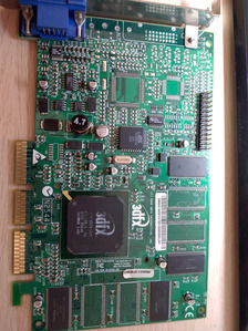
Hello, around 15 years back i got this Voodoo 4500 AGP with no fan on it.
The card was working fine (i attached a fan) up until a time when a short of the pcb fan pins (i also saw flash) made the card running at only AGP 1x in 3.3V boards only (AGP2X compatible boards) and with artifacts on the screen when running 3dmark (fine on windows). Previously the card could run in agp8x boards as well with 4X agp and no artifacts at 3dmark or games.

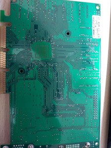
I had attached some photos of the card as it stands today. I observe no obvious shorts but yet again I am no so good with electronics. I noticed though two resistors that are named R00 that are shorted (got a tone in multimeter from one end to the other) whereas the others are not. Maybe it supposed to be that way since they are R00. Another thing is that the middle fan pin header is ground and it sounds strange to me as usually this is the 12V rail.

Please let me know if you have any idea of what to look? I believe it can be saved.
Thanks in advance, John

Attachments

Last edited by nosdio on 2023-11-01, 14:37. Edited 1 time in total.

Reply 1 of 8, by DerBaum

User metadata
Rank Oldbie
Rank
Oldbie
nosdio wrote on 2023-08-12, 11:44:

1) ...a short of the pcb fan pins (i also saw flash)...

2) ...since they are R00...

3) ... the middle fan pin header is ground...

1) What was shorted? PWR to GND ? Or PWR to SIGNAL?

2) Exactly... they are just bridges without any resistance.

3) Thats right. The middle pin is connected to ground planes on both sides of your PCB. And the pictures on the web show cards with a black cable there wich is usually ground.

FCKGW-RHQQ2

Reply 2 of 8, by nosdio

User metadata
Rank Newbie
Rank
Newbie
DerBaum wrote on 2023-08-12, 14:57:
1) What was shorted? PWR to GND ? Or PWR to SIGNAL? […]
Show full quote
nosdio wrote on 2023-08-12, 11:44:

1) ...a short of the pcb fan pins (i also saw flash)...

2) ...since they are R00...

3) ... the middle fan pin header is ground...

1) What was shorted? PWR to GND ? Or PWR to SIGNAL?

2) Exactly... they are just bridges without any resistance.

3) Thats right. The middle pin is connected to ground planes on both sides of your PCB. And the pictures on the web show cards with a black cable there wich is usually ground.

Thanks for answering
2 and 3 all OK then
I am sorry but can't remember i was trying to measure the voltage coming from the card's fan pin from the back side..sorry really can't tell. It was hooked up to an 815 motherboard. Probably the flash was from the mobo although there are no visible burned SMDs
OMG yes...now i remember. Since then the AGP slot of this particular motherboard does not work anymore while the rest mobo works fine, but this is for another episode...
If i would have to bet on it, i would say red with ground because the voltage was from red so the nearest is ground. The multimeter tip sorted it.
PPL make mistakes...i know.. 🙁

Reply 3 of 8, by DerBaum

User metadata
Rank Oldbie
Rank
Oldbie

I see 2 parts near the VGA connector (Q1 and Q2) these are N-Channel Mosfets. They are IRF7811A https://datasheetspdf.com/pdf-file/284041/Int … fier/IRF7811A/1

With the card not connected, check if you have shorts from S to D to G ... check all combinations for shorts on both chips. My best guess is that one of them should be for the 5v rail and one for the 3.3v rail.
PIN1 is on the corner where no text is on the chip.

FCKGW-RHQQ2

Reply 4 of 8, by nosdio

User metadata
Rank Newbie
Rank
Newbie
DerBaum wrote on 2023-08-13, 01:15:

I see 2 parts near the VGA connector (Q1 and Q2) these are N-Channel Mosfets. They are IRF7811A https://datasheetspdf.com/pdf-file/284041/Int … fier/IRF7811A/1

With the card not connected, check if you have shorts from S to D to G ... check all combinations for shorts on both chips. My best guess is that one of them should be for the 5v rail and one for the 3.3v rail.
PIN1 is on the corner where no text is on the chip.

@DerBaum Many thanks for your help once again. I checked and here is the results:

Q1: leg 1 to 3 are shorted together (from the datasheet i understand that this OK) but also to ground and PIN 2 on the Fan pin of the card!!
leg 8 to 5 are shorted together (from the datasheet i understand that this OK), pin 1 to 4 are not shorted to 8, i think again this OK but i do not understand how the "gates??"/arrows work.

Q2: leg 1 to 3 are shorted together (from the datasheet i understand that this OK), leg 8 to 5 are shorted together (from the datasheet i understand that this OK), pin 1 to 4 are not shorted to 8, again my understanding like Q1.

So as far as i understand i need to replace a IRF7811A for Q1, correct?

Reply 6 of 8, by DerBaum

User metadata
Rank Oldbie
Rank
Oldbie

I am not the best in searching failures online. Maybe somebody else has better understanding of the circuit.
There are several things i dont know and i would find out by measuring.
Pin3 of the fan should be the feedback of the RPM to the card. I cant see the trace (because its probably inside the board) so i dont know if the pin is maybe pulled up or down by a resistor.
1-3 (S[ource) of Q1 (and Q2) should be ground if im not completely wrong...

FCKGW-RHQQ2

Reply 7 of 8, by nosdio

User metadata
Rank Newbie
Rank
Newbie
DerBaum wrote on 2023-08-19, 20:41:
I am not the best in searching failures online. Maybe somebody else has better understanding of the circuit. There are several t […]
Show full quote

I am not the best in searching failures online. Maybe somebody else has better understanding of the circuit.
There are several things i dont know and i would find out by measuring.
Pin3 of the fan should be the feedback of the RPM to the card. I cant see the trace (because its probably inside the board) so i dont know if the pin is maybe pulled up or down by a resistor.
1-3 (S[ource) of Q1 (and Q2) should be ground if im not completely wrong...

Ok thank you for your help. If anyone else can help please do so.
I can replace both Q1, Q2 and nearby SC1102CS
Thanks again.

Reply 8 of 8, by nosdio

User metadata
Rank Newbie
Rank
Newbie
DerBaum wrote on 2023-08-19, 20:41:
I am not the best in searching failures online. Maybe somebody else has better understanding of the circuit. There are several t […]
Show full quote

I am not the best in searching failures online. Maybe somebody else has better understanding of the circuit.
There are several things i dont know and i would find out by measuring.
Pin3 of the fan should be the feedback of the RPM to the card. I cant see the trace (because its probably inside the board) so i dont know if the pin is maybe pulled up or down by a resistor.
1-3 (S[ource) of Q1 (and Q2) should be ground if im not completely wrong...

@DerBaum many thanks again for your posts. The card is fixed, i changed the first Q1 and the card is running again. It needs testing but it seems fine.
Runs Undying in SIS mobo with P4 and no issues. Maybe the ultimate test would be an AGP 1.5V mobo to see how it goes.
For the universal agp mobo the driver only has 1x, 2x and auto detect options.