VOGONS


First post, by Thomas82

User metadata
Rank Newbie
Rank
Newbie

Two weeks ago I bought a Dolch PAC 62. Everything seemed ok, except the display. When I turned it on, the display was readable, but with interference every few seconds. I thought that it could be the cables from the video card to the display.

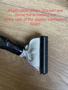
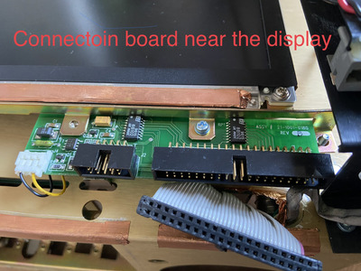
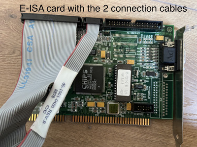
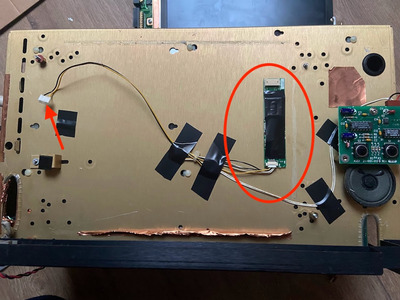
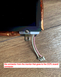
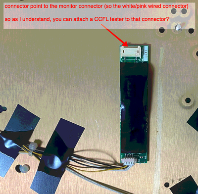
There are two cables in between: a 10-pin and a 40-pin ribbon flat cable. Near to the display connection board, the cables come together and can cause malfunction.

So I unmounted the cables, wrapped them with aluminum foil, taped it, and reconnected them. That worked! The display was as clear as never before! After that, I reassembled everything back together and replaced the cables in a good way. With that done, I made a stupid mistake I guess. When everything was reassembled I started the computer, and there was no display reaction anymore. The screen stays black 🙁

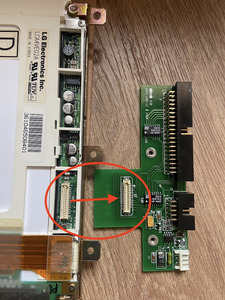
After inspection, I found that one of the cables had some foil coming out at the side of the display connectors. It could be that the foil caused a short circuit… But on the PCB from the displayside everything seems ok. I tried the computer with an external monitor, and it’s just working. So the mainboard and everything is still ok, except something at the display connection board I guess.. I even tried new ribbon cables (10-pins and 40-pins) but the display is not coming up anymore. I don't know what to do right now. I hope that there's somebody who can help me with this issue, cause I'm desperate.

I hope somebody can help. Thank you so much.

Attachments

  • IMG_0762.jpeg
    Filename
    IMG_0762.jpeg
    File size
    496.63 KiB
    Views
    772 views
    File license
    Public domain
  • IMG_0760.jpeg
    Filename
    IMG_0760.jpeg
    File size
    678.31 KiB
    Views
    772 views
    File license
    Public domain
  • IMG_0759.jpeg
    Filename
    IMG_0759.jpeg
    File size
    757.53 KiB
    Views
    772 views
    File license
    Public domain

Reply 2 of 12, by Thermalwrong

User metadata
Rank Oldbie
Rank
Oldbie

It's good that you know the VGA graphics is working so the graphics card itself is working right.

That PCB on the side of the LCD monitor, does it go into a connector on the back of the LCD? Perhaps thats been dislodged with all the removal/reinsertion of cables. Possibly remove the PCB and clean the contacts - should be a 41-pin connector like this /====\
Troubleshooting this beyond a dislodged connector is not easy in my experience, basically requires working backwards from the pinout of the LCD assuming that's known, to work out which signal does what.

Does the backlight come on?

You could just beep out / verify all 50 pins on 40+10 cable though while the cables are all in place while it's off. That's a good place to start since there are quite a few connection points (lcd connector > dolch lcd connector > lcd cable > video card)

Reply 3 of 12, by Thomas82

User metadata
Rank Newbie
Rank
Newbie
Thermalwrong wrote on 2023-09-10, 21:13:
It's good that you know the VGA graphics is working so the graphics card itself is working right. […]
Show full quote

It's good that you know the VGA graphics is working so the graphics card itself is working right.

That PCB on the side of the LCD monitor, does it go into a connector on the back of the LCD? Perhaps thats been dislodged with all the removal/reinsertion of cables. Possibly remove the PCB and clean the contacts - should be a 41-pin connector like this /====\
Troubleshooting this beyond a dislodged connector is not easy in my experience, basically requires working backwards from the pinout of the LCD assuming that's known, to work out which signal does what.

You could just beep out / verify all 50 pins on 40+10 cable though while the cables are all in place while it's off. That's a good place to start since there are quite a few connection points (lcd connector > dolch lcd connector > lcd cable > video card)

Thank you so much for your reply!
You gave me new thoughts of where to start now. I will get a multimeter to test all the pins, after, I will inspect the PCB board on the display side. It's some difficult to get it off, so I will look with my uncle next weekend. He has more experience in this cases.

I will keep you updated. Thanks!

Thermalwrong wrote on 2023-09-10, 21:13:

Does the backlight come on?

The monitor itself gives a short weak signal to the display for one second and then stays black. You can only see it in the dark when watching carefully. But it seems it picks up at least one signal..

Reply 4 of 12, by Thermalwrong

User metadata
Rank Oldbie
Rank
Oldbie

What's a weak signal, like noise on the screen?

What you're describing could be a backlight fault just as much as it could be an LCD signal fault - if it was a grey or white screen then the LCD side could be at fault but if the screen is just black, the first place to look is the backlight. That'll be a 2-wire cable going to the CCFL in the screen powered by an inverter board that's usually attached to the LCD separately from the LCD board you've pictured so far.

It'll usually have a small transformer on it and it makes the high voltage to run the CCFL. Since screen is black, best to check around there first and just make sure everything on that side is plugged in securely.

Reply 5 of 12, by Thomas82

User metadata
Rank Newbie
Rank
Newbie
Thermalwrong wrote on 2023-09-11, 16:18:

What's a weak signal, like noise on the screen?

What you're describing could be a backlight fault just as much as it could be an LCD signal fault - if it was a grey or white screen then the LCD side could be at fault but if the screen is just black, the first place to look is the backlight. That'll be a 2-wire cable going to the CCFL in the screen powered by an inverter board that's usually attached to the LCD separately from the LCD board you've pictured so far.

It'll usually have a small transformer on it and it makes the high voltage to run the CCFL. Since screen is black, best to check around there first and just make sure everything on that side is plugged in securely.

Thanks again for your answer. That weak signal isn't coming anymore.. I said a second, but it was more a millisecond. No noise but a very weak flash.

Today I already managed to get off the screen. Exactly as you described: I could take off the PCB display board, it was attached together with that connector (see picture). I cleaned the connector and put everything back together. Unfortunately no luck.

As you describe: The 2-wire cable connected to the display board is going to that small piece connected to the case with some tape (see the red circle). That's broken you think?
Do you think there's any hope left? What options are open?
Thanks.

IMG_0763.jpg
Filename
IMG_0763.jpg
File size
244.68 KiB
Views
642 views
File license
Public domain

Attachments

  • IMG_0766.jpg
    Filename
    IMG_0766.jpg
    File size
    248.87 KiB
    Views
    642 views
    File license
    Public domain

Reply 6 of 12, by sdz

User metadata
Rank Member
Rank
Member

That small board inside the red circle can give you a nice zap, avoid touching the output if it's powered on.

Use a strong flashlight and check if you can see any image on the display.

Reply 7 of 12, by Thermalwrong

User metadata
Rank Oldbie
Rank
Oldbie

Yep, can confirm, have been zapped a few times by the CCFL output voltage. I think it's in the hundreds of volts range.

Thanks for the extra pictures, so it's a 640x480 TFT and that adapter board looks like it's running the inverter as well. If it was me then it'd be the 40-pin was for the LCD data and the 10 pin is for the power or inverter power maybe. Looks like some of the chips near to where the inverter plugs in turn the backlight on&off - that 8-leg chip package is probably giving the power output and it's switched on/off by the "enable backlight" signal from the video card - that's what I've done with a similar one I hooked up on a single board computer.

Notice there's a green fuse (F1) by where the inverter cable connects, test that that has continuity and with the inverter unplugged but the monitor plugged in, see what voltage you see on the yellow&black cables. Should be somewhere from 5v to 19v usually.

The CCFL inverter itself looks quite standard, looks like maybe the brightness is controlled by that sub-board by the speaker too. That has its own fuse and they can also fail. Maybe while it's all off, pull off the black tape on the inverter to see what condition it's in as well as see if it has an identifiable part code
I'm thinking an LED backlight mod could be a cheap upgrade/fix but should be considered a last resort because it requires dismantling the LCD and hacking up some form of brightness control.

Reply 8 of 12, by Thermalwrong

User metadata
Rank Oldbie
Rank
Oldbie

Hmm, just thought of something else, can you swap out that 40-pin cable for a fresh regular 40-pin IDE cable? (not 80-pin and not with 1-pin blocked off) Or just get some replacement regular 2.54mm 2-row 40pin & 10pin cables.
There's a possibility that when the 40pin cable was separated that the insulation on a couple of the wires could have come off and the foil could be shorting it potentially. Trying another cable should eliminate that possibility even if your original fault returns.
If re-doing the shielding on the cable helped then maybe the two cables aren't in good condition after all. Or maybe there's something in the system making bursts of RF noise that disrupted the image periodically, shielding is a good way to fix that, I use copper tape or foil with tape over it the same as you do.

Reply 9 of 12, by Thomas82

User metadata
Rank Newbie
Rank
Newbie
Thermalwrong wrote on 2023-09-11, 19:09:
Yep, can confirm, have been zapped a few times by the CCFL output voltage. I think it's in the hundreds of volts range. […]
Show full quote

Yep, can confirm, have been zapped a few times by the CCFL output voltage. I think it's in the hundreds of volts range.

Thanks for the extra pictures, so it's a 640x480 TFT and that adapter board looks like it's running the inverter as well. If it was me then it'd be the 40-pin was for the LCD data and the 10 pin is for the power or inverter power maybe. Looks like some of the chips near to where the inverter plugs in turn the backlight on&off - that 8-leg chip package is probably giving the power output and it's switched on/off by the "enable backlight" signal from the video card - that's what I've done with a similar one I hooked up on a single board computer.

Notice there's a green fuse (F1) by where the inverter cable connects, test that that has continuity and with the inverter unplugged but the monitor plugged in, see what voltage you see on the yellow&black cables. Should be somewhere from 5v to 19v usually.

The CCFL inverter itself looks quite standard, looks like maybe the brightness is controlled by that sub-board by the speaker too. That has its own fuse and they can also fail. Maybe while it's all off, pull off the black tape on the inverter to see what condition it's in as well as see if it has an identifiable part code
I'm thinking an LED backlight mod could be a cheap upgrade/fix but should be considered a last resort because it requires dismantling the LCD and hacking up some form of brightness control.

Thanks again for your reply! Sorry for my delay, I had a busy week. Finally I have some time to look at this.

Your last reply (to try new cables) was the first thing I tried when the display failed, that was no solution unfortunately.

Checking the voltage of the yellow and black cables is a good suggestion. I have the feeling that the backlight is failing. If I understand it right, the yellow&black cabels are only to give voltage for the blacklight, right? (CCFL output).. If that's right the conclusion can be:

No voltage: the fuse has to be replaced/ there is something wrong with the connection/PCB to the power.
Voltage: it can be that the backlight is broken. I can try to check this with a strong flashlight like user 'sdz' suggests..

I think this will be the first I will try to check If i'm right? I will update you off course afterwards. I think it will be next weekend for another inspection.

Thanks a lot for now, you gave me new insights!

Reply 10 of 12, by Thermalwrong

User metadata
Rank Oldbie
Rank
Oldbie

The yellow and black wires are the low voltage DC power that runs the CCFL inverter, at probably 5v or 12v DC. That's what F1 is for, the high voltage part is the thin rectangular (highlighted as red oval) PCB stuck to the back of the monitor - there *should* be a connector with two wires (usually white & pink) going from the large connector on the inverter into the LCD where the CCFL bulb is situated. I don't see that in your pictures though?

To check out whether the CCFL itself is working well, you can buy a generic CCFL tester which is a little blue box that runs from 12v DC. Just disconnect the CCFL of the screen and plug it into the tester, then apply power to the tester, you don't even need to have the computer turned on to check it that way.
My original blue-box tester failed after a while and now I use a generic inverter, but it's cheap enough for testing and it includes both the smaller 2-pin (newer CCFLs) and larger 3-pin (industrial and older CCFLs) type connectors.

The backlight system has a few parts involved, so starting with whether the DC part is working is the best place to start from 😀 If you use a backlight tester, you can determine whether the fault is with the CCFL bulb itself (hard to replace) or with some part of the CCFL inverter system.

Reply 11 of 12, by Thomas82

User metadata
Rank Newbie
Rank
Newbie

Thanks again for your kindness and detailed information!!

Thermalwrong wrote on 2023-09-18, 20:54:

The yellow and black wires are the low voltage DC power that runs the CCFL inverter, at probably 5v or 12v DC. That's what F1 is for, the high voltage part is the thin rectangular (highlighted as red oval) PCB stuck to the back of the monitor - there *should* be a connector with two wires (usually white & pink) going from the large connector on the inverter into the LCD where the CCFL bulb is situated. I don't see that in your pictures though?

You're right! from the monitor, there are 2 wires (white/pink). The connector goes into the top connector of the CCFL board (see also picture).

screenshot_92.png
Filename
screenshot_92.png
File size
306.6 KiB
Views
475 views
File license
Public domain
Thermalwrong wrote on 2023-09-18, 20:54:

To check out whether the CCFL itself is working well, you can buy a generic CCFL tester which is a little blue box that runs from 12v DC. Just disconnect the CCFL of the screen and plug it into the tester, then apply power to the tester, you don't even need to have the computer turned on to check it that way.
My original blue-box tester failed after a while and now I use a generic inverter, but it's cheap enough for testing and it includes both the smaller 2-pin (newer CCFLs) and larger 3-pin (industrial and older CCFLs) type connectors.

The backlight system has a few parts involved, so starting with whether the DC part is working is the best place to start from 😀 If you use a backlight tester, you can determine whether the fault is with the CCFL bulb itself (hard to replace) or with some part of the CCFL inverter system.

I searched for a CCFL tester, but they are some pricey. I'm searching now if somebody in my neighbourhood has one to borrow. But can I test this also by checking the power out of the top connector? The power out of the CCFL board is only for giving power to the backlight of the monitor, right? So, if there is power than I can suggest it's ok, if there is no power, there is something else wrow (maybe fuse..). Or isn't that a good thought?

screenshot_91.png
Filename
screenshot_91.png
File size
502.88 KiB
Views
475 views
File license
Public domain

Reply 12 of 12, by Thermalwrong

User metadata
Rank Oldbie
Rank
Oldbie

Hmm, they're like €10 and it's really not something that people are generally going to have. If you deal with old computers often (I do) then it's definitely worth having a generic CCFL inverter that can run from 12v and connect up both later 2-pin and earlier 3-hole 2-wire inverter types. I use mine a lot - even after the original one failed I wired up a generic inverter to run from 12v and it can run both 2-pin and earlier 3-hole 2-pin inverters using the cable I took from the original CFL tester.

You can test the inverter if you know it well, like know its input voltage and general current consumption. I test out Toshiba inverters that I know run on 5v and consume 500 to 600ma on average where I know how to hook it up, but if you're not sure of what's what on the existing inverter, my suggestion is to bypass that black-box and see how the CCFL runs when run off of a totally different inverter.

If you can't test another inverter, check what the voltage is the yellow/ black wires from the LCD connector, since that's powering the inverter and a fault there could cause the black screen you're seeing.
I recommend not trying to test the CCFL connector end since that's in the hundreds of volts area and I don't recall whether it's AC or DC (the CCFL itself is best to test that), stick with the low voltage side for now.