VileR wrote on 2023-06-25, 18:28:Nice!
Speaking of the display: would it be possible to improve the centering of the active area within the emulated monitor? As far as I can tell, +HRES modes (80-col text) are shifted far to the right, while -HRES (everything else) is way off to the left
GloriousCow wrote:The version of MartyPC you're using returns the raster to the left side of the screen at the end of hblank. So it's not just the HorizontalSyncPosition that matters, but SyncWidth as well. You are correct in that the HorizontalSyncPosition is effectively the same in 80 column and 45 column mode, but SyncWidth is programmed as 10 in both modes so in 40 column mode the SyncWidth is effectively twice as wide. I already decided that waiting for end of hblank was probably incorrect.
Hello!
I'm the founder of Blur Busters and TestUFO, and I'm the resident expert of the "Present()-to-photons" black box on PC based systems.
Most of you have figured this out by now, but, I'd like to provide a useful diagram that enlightens many people a bit more quickly.
The display is not "deciding". It's definitely something digital before the analog side (either spewing out of the CRTC, or some digital trigger circuit between the CRTC or the display itself)
Terminology vary a lot between communities, e.g. broadcast vs programmers vs manufacturers vs API naming nomenclature. e.g. "Overscan" = "Porch", or "VBLANK" = "VSYNC", but they can be different, if one community considers VBLANK as (VSYNC + vertical porches), but another community does not. It is sort of a "Semantics Shemantics" rabbit hole, but for simplicity, I'll stick to Blur Busters's usual terminologies for the purposes of this post. A specific API or register named "SyncLength" might refer to only the sync pulse, or the entire blanking interval (sync and porches) -- on different platforms. I don't know what 5150 does terminologically / signally, but it merits keeping in mind.
So, here are some generalities:
- What the software thinks is not always aligned with the analog signal.
- What some elsewhere call HBLANK often accidentally includes horizontal back porch (left overscan) and vertical back porch (right overscan), in addition to the real HBLANK.
- What some elsewhere call VBLANK often accidentally includes vertical back porch (top overscan) and vertical front porch (bottom overscan), in addition to the real VBLANK.
- What some elsewhere call OVERSCAN (for borders) isn't always pixel-aligned with signal-level horizontal back porch and vertical back porch.
- Most color-border overscan is actually not part of the signal vertical back porch nr vertical front porch!
- The (turned-off but sometimes still spewing a few latent electrons) CRT beam is held stationary beyond left edge of tube if it's finished moving there during true horizontal signal blanking (HBLANK analog side)
- The CRT beam yoke electromagnets instantly starts deflecting left-to-right upon analog signal edge transition from HBLANK to signal-level overscan (horizontal back porch)
- Thus, horizontal image position on a real tube is typically very dependant on the exit out of signal HSYNC (transition from signal HSYNC to left overscan).
So you've got two terminological overscans (sometimes three!) involved in concentric rectangles around your addressable graphics -- the color borders overscan and the signal overscan.
Most are usually unaware that overscan actually contains two overscans on some platforms.
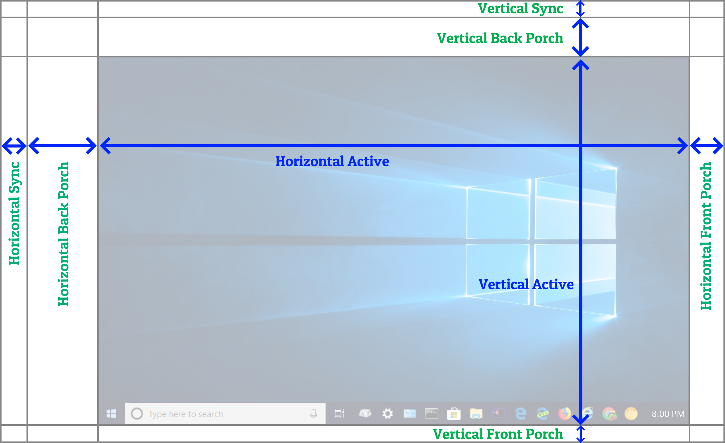
Here is a modified version of my earlier signal structure diagram, to highlight the two overscans.
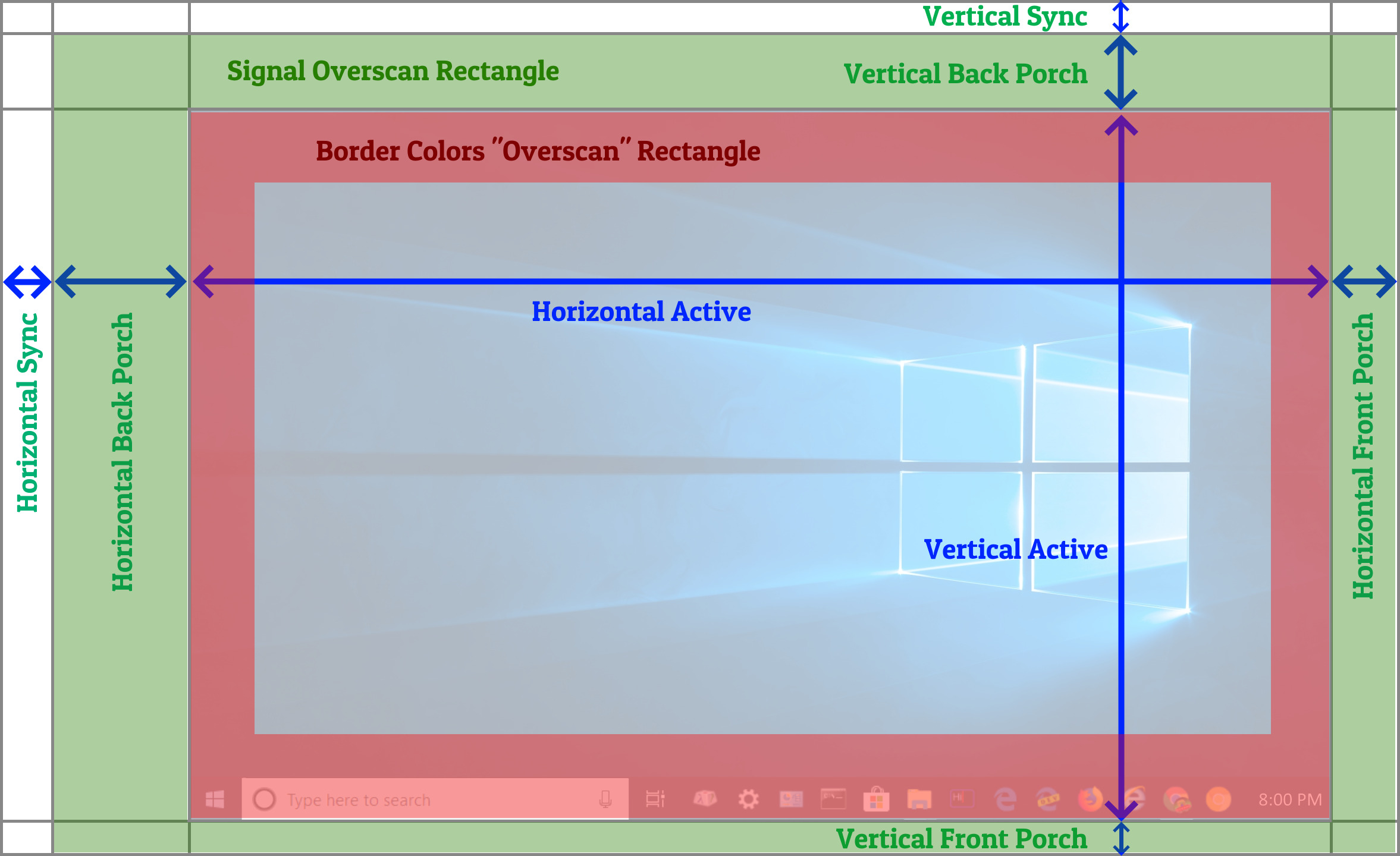
Sometimes on some platforms, the overscan merges both only on a certain platform (e.g. border color in front porches, and using a very thin black-color back porch). Or, depending on platform, signal, and signal type, there can be three concentric overscan rectangles, e.g. a different-color padding between the outer signal overscan and inner border-colors overscan, depending on the signal used.
In programming some platforms, there can be some transfers between all, e.g. most CRTs will be fine if you randomly transfer pixel between inner/outer every line (horizontals) or every frame (verticals), as like color in actual signal overscan, or signal overscan in what was normally border color. It's typically harmless to "slush" a little that way, as long as you don't bleep around with those "blanking"->"porch" signal transitions, and you don't bleep around with those clocks per line or per refresh. Since overscan is really just usually black pixels historically. In some signal standards like NTSC, porches are simply same as black pixel voltage (7.5 IRE) and sync is below black pixel voltage (0 IRE). RGBI does not work the same way, but they still have use signal blanking and signal porches too on the analog side.
Sometimes you've got some weirdnesses on some signals of merged overscans only on certain edges, where the back porch is normal specification but the front porch is out-of-spec with non-black pixels (merged bordercolor with front porch) -- whether by programming tricks or quirks on specific platforms. This, too, typically works on real tubes, though can create side effects, like edge distortions or slight black level risings from the electron backscatter of the beam hitting the inside of the tube outside the phosphor mask area. So it's not always concentric rectangles.
If there are still problems after some debugging -- perhaps some dummy padding is being kicked/slushed around a bit from abusing CRTC like a TIA. Your logical sync stuff may or may not line up with the signal sync stuff.
I am not an expert on the CRTC, just the generic signal layout found in all video signals, analog and digital, including components that modifies analog horizontal position.
From the existing registers, some math between HorizontalSyncPosition and SyncWidth may allow you to determine where the signal HSYNC ends (overscan starts), since that's the important image-positioner dependency on a real CRT, unless some black box circuitry is executing some automatic compensation.
There's possibly three components (horizontal front porch, horizontal overscan, horizontal back porch) you're going to have to math-out from the registers you are successfully emulating. Depending on what the registers really creates analog-side, it is possible to ignore the front porch as part of your mathematics, if you don't need it to determine the size of back porch. But if you aren't emulating enough data in order to determine the exact moment signal HSYNC falling from true->false (transition from HSYNC to overscan) that dictates horizontal image positioning on a real CRT tube, then you're going to have to reverse-engineer with an oscilloscope next.
You might be witnessing a situation where you've got thicker/thinner HBLANK and thinner/thicker porches (still same clocks per line). Or where you've got your HBLANK offsetting left/right ("thinner back porch/thicker front porch" situation) Either way same clocks per line. Most CRTs work fine that way, although the image position usually shifts left/right if you transfer timings between the front-vs-back horizontal porch.
However, your situation of:
- Horizontally shifted image in the emulator
- Constantly centered image on real machine
Might be from the emulator assuming incorrect end-of-hblank position, like not knowing where the signal-hblank transitions to signal-hbackporch, which might not be easy to determine (?) without a bit of further reverse engineering. Most emulators simply treat the blanking intervals as one monolithic block without all those pesky little components...
There's some sheningans that seems to shift blanks around a bit -- but it's definitely something before the analog side, as the beam electromagnets only starts deflecting the cathode ray from left-to-right upon the edge-transition from hblank to horizontal back porch. So reverse engineer that edge transition with an oscilloscope! The signal HSYNC and VSYNC (also called HBLANK or VBLANK, if it's not including the porches) "holds" the turned-off beam stationary at the very left (when in HSYNC) and very top (when in VSYNC) if it's already finished moving there, and the beam doesn't start moving until the edge-transition into porch (signal overscan).
To help debug how the CRTC decides to mis-align signal blanks/overscan timings with assumed blanks/overscans -- I suggest connecting an oscilloscope.
There may be multiple possible oscilloscope-debug workflows, such as connecting Oscillope Input #1 to the analog signal of a real IBM CGA monitor during executing 8088 MPH as well as AREA 5150, while connecting oscilloscope input #2 to some debugging trigger (e.g. an Arduino logic-monitor "listening into a CRTC pin and triggering a marker pulse when a specific value is written to specific registers") -- and watching the offsets between #1 and #2 on the oscilloscope screen. Finding the certain patterns where the Ground Truth changes (signal edge of hblank suddenly transitioning to horizontal back porch), and modifying the emulator to be more compatible, perhaps. There may be easier oscilloscope debugging workflows, but an oscilloscope may be needed to debug the offset between assumed vs actual. Reverse engineer those sync->porch transitions. This Is The Way </mandalorian>
(Did you know? This signal structure has been around for a century, still in 2020s DisplayPort, even in a 240Hz DSC G-SYNC signal! It is the topology found from 1930s analog TV broadcast signal through 2020s DisplayPort (in digital format), so it's impressive we've stuck to the same raster topology for a century! The digital transition kept the analog timings like time-paddings and comma separators so precisely that a generic passive synchronous 1:1 VGA->HDMI adaptor (in the era before full HDMI packetization) works perfectly timing-wise. So everything's still there digitally in a 2020s DisplayPort signal as an analog signal of the same timing parameters. Although modern DP/HDMI packetization and multiplex (audio packets, etc) jitters by an error margin of about 1 scanline nowadays. But that, today, even is still good enough for line-based beam racing today. It's just an obvious defacto serialization of 2D imagery into a 1D spew threw a cable / radio / drinking straw / etc)
_____
Some more background: I am in 25 research papers (purple "Research" tab at Blur Busters website). I don't have much demoscene cred, but I cut my teeth on Commodore 64, with 6502 and beam racing experience.
I'm the author of the still-WIP Tearline Demo (volunteers welcome) for treating any tearing-capable GeForces/Radeons/Intel like an Atari TIA (beam racing modern GPUs), I posted videos at pouet.net including real-raster Kefrens Bars on NVIDIA GeForce GTX 1080 GPU a few years ago ("Tearlines Are Just Rasters"), under Windows in mere C# HLE and the cross-platform MonoGame game engine. I also recompiled it on a Mac, and most of it worked, so it was crossplatform-capable, albiet with lots of raster jitters. Code was shelved, but with some babying, could become the world's first crossplatform rasterdemo, tolerating a bit of very fun raster jitter from all the varying error margins of the various platforms, abusing a number of modern GPUs like an Atari TIA, rendering unscreenshottable beamraced graphics on the fly. If any democoder would like to resurrect this concept and/or teamup and include me in the credits, I'm open. Time is limited on my side, but I can teach modern-GPU beamracing basics.
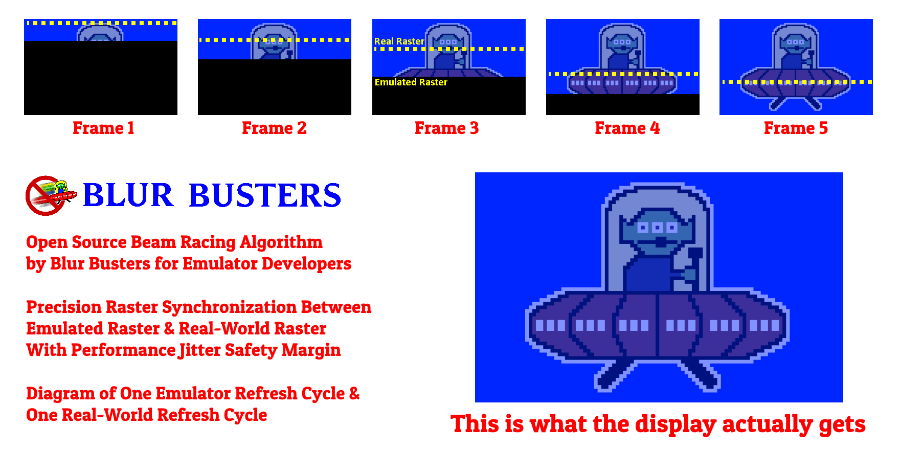
Some emulators (Toni's WinUAE and Tom Harte's CLK) now use my findings to create a new lagless VSYNC mode, with sub-refresh latencies, by Present()ing frameslices during VSYNC OFF mode later blocks of scanlines to the GPU even while the GPU is already video-outputting earlier scanlines, from an invention of mine called "frameslice beam racing", which has been named "lagless vsync" by Toni of WinUAE Amiga Emulator. Windows D3DKMTGetScanLine() is sometimes used, or a raster-estimate via time-offset between consecutive VSYNCs, with Present()+Flush() precisely timed by CPU busywait loops, during a Full Screen Exclusive VSYNC OFF mode (that has ugly tearing unless the tearing is hidden by beamracing). This works just fine since there's a performance jitter safety margin in frameslice beamracing. Since WinUAE/CLK respective lagless vsync races ahead of the real displays' raster, VSYNC OFF never tears, and is a solid lagless "perfect VSYNC ON lookalike" emulated mode, e.g. 600fps VSYNC OFF at 10 frameslices per emulated 60Hz refresh cycles. And tearing/glitching never appears unless the system jitters 1/600sec "late", etc. Assuming the realworld raster is inside the jitter margin of one frameslice ago, aka (0.5 + 1)/600sec, this is only ~1.5/600sec input lag behind a real machine! (Configurable higher or lower, e.g. 1200fps, 1800fps, etc). Thin VSYNC OFF frameslices that are beamraced onto the screen, appended to the still-invisible "tearline" before the beam hits it. That way, you can stay tearingless. That creates subrefresh-latency "VSYNC ON" done via raster beam racing software tricks on VSYNC OFF -- with no tearing! Some GPUs can do over 2000 frameslices per second in WinUAE, creating sub-1ms lag relative to original machine! While not useful for emulators playing demoscene content, but great for gaming in an emulator to have original-machine lagfeel -- it is pretty clever.
