superfury wrote on 2024-02-04, 14:53:
But unlike those lower 4 bits, the upper are always driven by the MID inputs? What are those MID inputs?
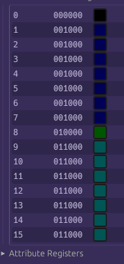
M1D is the attribute byte. It's an entire byte - 3-4 bits for foreground color and 3-4 bits for background color, but as we have seen the 3rd and 7th bit gets borrowed for other purposes, depending.
superfury wrote on 2024-02-04, 14:53:
OK. So those MID lines are the attribute number selected (from the text mode attribute generator. Bit 3 is used afaik to select character set A or B? Is that what those attribute inputs are for?)?
whats an attribute generator? The Attribute Controller receives the raw attribute byte. It needs the attribute byte to know what colors to emit for foreground and background of the font glyph span it receives.
superfury wrote on 2024-02-04, 14:53:
What do those lower 4 bits of the character index have to do with attribute inputs and text mode/graphics mode for attribute inputs? Doesn't the attribute controller just receive attribute inputs? Why multiplex the character number depending on text mode? What does U23 do with the character number (MID0-3)? And MID4-7 is always connected for something (blink on MID7? What's it's purpose)? Is MID the attribute byte and C0-C3 on it's inputs the attribute for graphics modes?
The lower four bits are multiplexed as they receive serial color information in graphics mode - one 4bpp pixel index per clock. In graphics mode, ATR4-7, and CC0-CC7 aren't used.
The Attribute controller basically has two operational modes - serial and parallel, again controlled by the S/L input. (Shift Load).
In text mode, the Attribute Controller receives the attribute byte on ATR0-ATR7, this comes from Plane 1, and the 8-pixel row 'slice' of glyph font data on CC0-CC7. You can see these come from M2D , or Plane #2, where we know fonts are stored. Thus in text mode, the Attribute Controller operates in parallel mode, since it receives the entire 8-bit glyph row span at once instead of being fed pixel data clock by clock.
Note that the Attribute controller has no connection to Plane 0. It has no idea what character it is drawing, other than whether the character is a line drawing character or not (indicated by the LG input)
When a character is read from plane 0 there is discrete logic that calculates the address of the corresponding font glyph by combining the character index with the CRTC's character row counter. This is accomplished by chips U12 and U3 on Sheet 5. You can see U12 takes RS0-RS4, which is the 5-bit row counter from the CRTC, latched by U20 on page 3. It looks like it's turning addresses into row counters, which might be a bit confusing. What's going on is that the CRTC is also multiplexing its own pins between address and row count. The 'REF' pin signals which one is being output, allowing U20 to latch the row counter at the appropriate time.
superfury wrote on 2024-02-04, 15:11:
Chip U31 pin 12, marked GP0 ("GRAPHICS" output) going to U23's _GRAPHICS input. On page 5 it's inverted before being sent to U23?
The same pin is connected to CDSEL0(PROM pin A7 on U48?) on the other graphics chip.
Ah. Well, I would imagine GP0 tied to GRAPHICS is controlled by the G/A bit in the Graphics Controller's Miscellaneous Register. The sequencer also has to be told we are in text mode via it's own A/G bit in the Memory Mode register, because it is responsible for switching the Attribute controller into parallel mode via the S/L bit. A lot of these redundant registers make sense when you realize that each chip has a specific role to perform. It would be interesting to properly emulate what happens if they are not set correctly to match each other...
MartyPC: A cycle-accurate IBM PC/XT emulator | https://github.com/dbalsom/martypc