VOGONS


First post, by termynuss

User metadata
Rank Newbie
Rank
Newbie

Just as a quick preface: I've always loved wavetable daughterboards, despite their lack of support and overall quality. Though I have moved on to better modules (Roland SC-55st instead of SCD-15 and Yamaha MU-10 instead of DB50XG), I always still had the old "lesser" wavetables that sat around being useless, mainly my SoundscapeDB, Waveblaster II, and AdWave 32s. Sure, they aren't the best wavetables, but if I have them why not put them to use?

So for a long time I searched out an answer to find the perfect soundcard for mounting the old wavetables on. I tried just about everything -- Crystal-chipped (4xxx -- Terratec Maestro/Magic S20/SoundGalaxy) boards, ESS boards, Opti boards, Aztech boards, nothing seemed to work quite right though, there would always be some game that had a nasty deficiency with some card that it never had with a Soundblaster Pro 2 or 16. Sure, SB16s are okay for some daughterboards, but the support is finnicky at best and other daughterboards refuse to work period -- plus my IRQ 2/9 is already used by my MPU-IPC-T.

So tired of the endless search for the non-existent perfect card, I decided to take a different approach. I decided it was time to make a wavetable module. At first, I thought about picking up a Korg NS5R, which has daughterboard support built-in to the module, but I could never find very good information on it and you were supposed to send in your daughterboard to Korg to have them custom service the module to properly accept one. So that one wasn't going to work. I played with the idea briefly of paying out the wazoo for an MPU-401/AT, but it had been a long time since I had seen one for sale, and I wasn't ready to shell out around one-hundred dollars for yet another ISA card when I already have an IPC-T hooked up.

I then dug around usenet and found those old schematics from the DB50XG owner group that detailed how to build a PCB for this purpose, but from further digging it seemed that the instructions had come from an old German company's design of a wabetable module. The problem I found is that some of the parts' nomenclatures are very odd, and some of the resistors (such as the 10kΩ8 variable inline resistor) are very rare and hard to find.

So with help from my electronics hobbyist father, I decided we needed to retool the specifications to make a cheaper and more plausible alternative. After getting the specifications for all the parts, finding alternatives, and digging around for hours at a local electronic components warehouse in the sweltering heat, we finally had come up with a decent solution. If there is interest, I will see about making an entire write-up, step-by-step, to making one of these modules with a new parts and schematic list.

Anyway, we finally finished it last night, and it's great. Finally, the daughterboards are free of poor MPU-401 ports, are kitted with MIDI out and thru, and have received their own amplifier and true independent volume control. Of course, for the finishing touch, we had to make a case for it, to turn it into the true old moniker given to these modules-- "black boxes."

So without further ado, here she is:

module.jpg
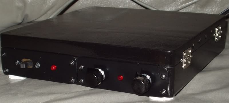
Here we have the case of the module. As you can see here on the front we have the power switch, the power LCD, left volume control, the MIDI-send LCD (this blinks as MIDI data is being sent), and right volume control. Not pictured on the back of the unit are the two line-out jacks, the two speaker-out jacks (the amplifier powerful enough on this thing that you could easily drive speakers with them), and the MIDI-thru and MIDI-out DIN jacks.

inside.jpg
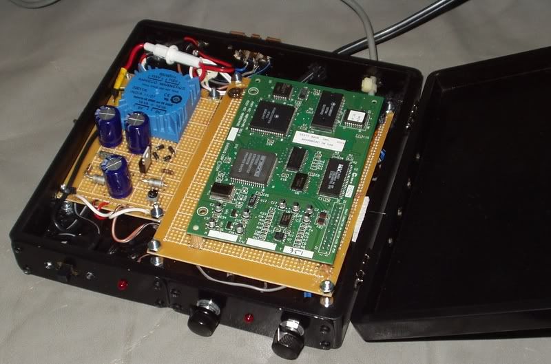
Open it up from the side and who do we have here? It's a SoundscapeDB plugged into the 26-pin header! On the left is the custom-made power supply, and the right is obviously the component board. To save patch cables, the module does not have a MIDI-In jack, but uses a hard-wired MIDI cable instead. Perhaps not the most practical thing, but it can change whenever.

board.jpg
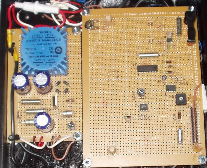
And here, lastly, is the inside. This was before I hooked in the MIDI-thru and out, so it isn't the 100% completed package, but everything else was finished at this time. As you can see, the component breadboard is pretty bare -- it'd be a lot smaller but I wanted a good base for the daughterboards in which I could mount permanent standoffs. It works pretty well so I'm not complaining.

So I guess the lesson is that people who don't have ISA cards, who don't want to settle for poor "clones", or who just want to give their daughterboards a second chance, should not give up hope in finding a good solution. Making one of these modules is definitely doable, even for the amateur, and finally being rid of nasty MPU-401 ports or any host sound card is a relief. Plus it sounds great!

Reply 1 of 9, by Mike 01Hawk

User metadata
Rank Member
Rank
Member

Amazing, wonder what Cloud and Great will have to say.

I guess I should consider myself lucky to find a MPU-401/at on the bay... and well, not so lucky considering what I paid for it.

Dell Optiplex Gxpro: Built solely so I could re-live my SB16 days properly with newly acquired sound pieces: MT-32, SCB-55, and DB50xg 😀

Reply 3 of 9, by termynuss

User metadata
Rank Newbie
Rank
Newbie
Silent Loon wrote:

How does it sound, compared to the wavetable header/soundcard solution?

It sounds a bit better, mostly because of the quality of the audio jacks and amplifier used. Wavetable daughterboards are pretty much their own audio device, so any upgrade in quality comes really from whatever it is being filtered through. Not having to deal with a soundcard's electronic interference from other components in the computer, or other sources of noise such as MIC or LINE inputs also bolsters the sound quality. Using separate, clean gold stereo jacks as pure line output sounds really great.

The best part is the total parts cost around 35 dollars to build with tax.

Reply 5 of 9, by QBiN

User metadata
Rank Oldbie
Rank
Oldbie

I had gone through some of the same academic exercises to build a similar box a couple of years ago, but never followed through with sourcing all the parts.

I, for one, would love to see the parts list... then head to the local Fry's to start of my own!

Reply 6 of 9, by gerwin

User metadata
Rank l33t
Rank
l33t

Nice work! All the more rewarding if you build and solder such items yourself.

Recently I soldered a small cpu-fan speed-control unit and a stereo-reverser for my midi daughterboard connector. Currently I am quite content with just keeping the daughterboards on host cards. Inside the PC there is 5Volt and 12V plus and minus easily available, with an external module most parts are aimed at an indepandant power supply. But it still seems like fun to make a external module anyways, or a module that is external audio-wise, but just uses the PC-power supply?
PS: This article seems quite complete and gives a more compact solution than other building plans I have seen, but I don't know yet if it has good features:
c't 1/97, S. 328: Midi-Expander

Reply 7 of 9, by termynuss

User metadata
Rank Newbie
Rank
Newbie
dh4rm4 wrote:

how much would you charge to produce these in small numbers? would you be open to releasing schematics and parts lists?

I'm not sure about producing them, but I am in the process of making a new guide.

QBiX wrote:

I, for one, would love to see the parts list... then head to the local Fry's to start of my own!

You live in DFW? I have a better place for you to go to than Frys 😀 .

gerwin wrote:

Recently I soldered a small cpu-fan speed-control unit and a stereo-reverser for my midi daughterboard connector. Currently I am quite content with just keeping the daughterboards on host cards. Inside the PC there is 5Volt and 12V plus and minus easily available, with an external module most parts are aimed at an indepandant power supply. But it still seems like fun to make a external module anyways, or a module that is external audio-wise, but just uses the PC-power supply?
PS: This article seems quite complete and gives a more compact solution than other building plans I have seen, but I don't know yet if it has good features:

Yeah, one of the reasons for building it was to be completely rid of the bounds of the case (and any possible interference inside), as well as having the ability to use the module with my other computers and keyboards. I originally did hook it up to the power in the PC, so it is definitely possible, but I wouldn't really recommend it if you're looking to make a truly modular solution.

The article you posted would end up being the same size really if you used the same process I did. The plans I worked off of originally called for a PCB as well, but well, having a PCB wasn't the most realistic requirement for me and breadboards were in high supply. My German isn't the best, but it looks like a decent schematic, though the parts list is very exact and may not be the best for everyone -- it would have been nice had they just listed the straight properties of the components instead of the names on many of them. It seems to be just as complete though!

Reply 8 of 9, by gerwin

User metadata
Rank l33t
Rank
l33t

I checked again, but the article I linked to is without an amplifier like yours, the waveblaster output goes straight to the connectors. It has a DIN input besides another socket marked 'mac' as in macintosh?. hmm...

Reply 9 of 9, by Cloudschatze

User metadata
Rank Oldbie
Rank
Oldbie

Very nice job, Termynuss!

I'm still acquiring components to complete the Elektor design, the plans for which can be found in this thread. Certainly not the cheapest boondoggle, to say the least.

To have worked your own design, and for less than thirty-five dollars, is quite the accomplishment. 😀