VOGONS


First post, by Babasha

User metadata
Rank Oldbie
Rank
Oldbie

Hi!

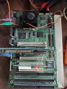
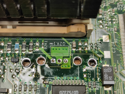
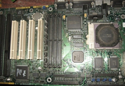
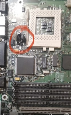
I need help with identification of lost voltage regulator on INTEL AA-654850-206 Advanced/ML Marl motherboard.
I highlight it position with the red on picture. Maybe it CS5702-1?

Tnx!

Attachments

Last edited by Babasha on 2022-05-18, 20:49. Edited 1 time in total.

Need help? Begin with photo and model of your hardware 😉

Reply 1 of 21, by dionb

User metadata
Rank l33t++
Rank
l33t++

Can't help with the transistor, but can help you with the name. That's an Intel Advanced/ML "Marl" board. Perhaps you can find more with that, or others with the same board might recognize it easier.

Reply 2 of 21, by debs3759

User metadata
Rank Oldbie
Rank
Oldbie

It looks like it's the voltage regulator you need. See page 7 of https://www.ultimateretro.net/motherboard/man … 21179229398.pdf to confirm this.

See my graphics card database at www.gpuzoo.com
Constantly being worked on. Feel free to message me with any corrections or details of cards you would like me to research and add.

Reply 3 of 21, by Babasha

User metadata
Rank Oldbie
Rank
Oldbie
debs3759 wrote on 2022-05-18, 19:54:

It looks like it's the voltage regulator you need. See page 7 of https://www.ultimateretro.net/motherboard/man … 21179229398.pdf to confirm this.

Yep! So i need a photo with readable part number of this voltage regulator.

Need help? Begin with photo and model of your hardware 😉

Reply 4 of 21, by snufkin

User metadata
Rank Oldbie
Rank
Oldbie

With a decent photo of the front and back of the board in the area around the regulator then it might be possible to work out how it's wired up, and from that have a guess at what the part ought to be. Only worth trying that if no one else can find out what the part really is.

Reply 7 of 21, by Babasha

User metadata
Rank Oldbie
Rank
Oldbie
quicknick wrote on 2022-05-19, 22:08:

I have a late replica of this board, made by InBus Engineering (aka "the world's largest supplier of retired Intel Motherboards and systems.").

The vrm is a LT1585A.

Great! Thank you!

Need help? Begin with photo and model of your hardware 😉

Reply 8 of 21, by Adriand1281

User metadata
Rank Newbie
Rank
Newbie
quicknick wrote on 2022-05-19, 22:08:

I have a late replica of this board, made by InBus Engineering (aka "the world's largest supplier of retired Intel Motherboards and systems.").

The vrm is a LT1585A.

Hi. I have the same problem, but I need the second line from the layout to identify this element. It'll probably say "ACT" there, but I'd like to be sure. If you could take a peek to clear my doubts. Thank you in advance

Reply 10 of 21, by majestyk

User metadata
Rank Oldbie
Rank
Oldbie
Adriand1281 wrote on 2022-08-19, 19:08:

Hi. I have the same problem, but I need the second line from the layout to identify this element. It'll probably say "ACT" there, but I'd like to be sure. If you could take a peek to clear my doubts. Thank you in advance

There are only 2 versions of this regulator: one with adjustable output voltage (LT1585ACT) and one with 3.3V fixed (LT1585ACT-3.3).

https://www.analog.com/media/en/technical-doc … ets/1585afa.pdf

(Some manufacturers use the "ADJ" marking for the adjustable version).
As far as I understand the manual the board is for 3.3V CPUs only so I assume it´s LT1585ACT-3.3.

To make 100% sure you can check if pin 1 of the regulator is connected to ground. If so, -> LT1585ACT-3.3

Reply 11 of 21, by Adriand1281

User metadata
Rank Newbie
Rank
Newbie
majestyk wrote on 2022-08-19, 20:13:
There are only 2 versions of this regulator: one with adjustable output voltage (LT1585ACT) and one with 3.3V fixed (LT1585ACT-3 […]
Show full quote
Adriand1281 wrote on 2022-08-19, 19:08:

Hi. I have the same problem, but I need the second line from the layout to identify this element. It'll probably say "ACT" there, but I'd like to be sure. If you could take a peek to clear my doubts. Thank you in advance

There are only 2 versions of this regulator: one with adjustable output voltage (LT1585ACT) and one with 3.3V fixed (LT1585ACT-3.3).

https://www.analog.com/media/en/technical-doc … ets/1585afa.pdf

(Some manufacturers use the "ADJ" marking for the adjustable version).
As far as I understand the manual the board is for 3.3V CPUs only so I assume it´s LT1585ACT-3.3.

To make 100% sure you can check if pin 1 of the regulator is connected to ground. If so, -> LT1585ACT-3.3

I will check the short to ground on leg No. 1. And I have one more question. This stabilizer is quite hardly available and I would have to order it from China, is it possible to use a replacement or impulse converter there? As you think, at least for testing.

Reply 12 of 21, by majestyk

User metadata
Rank Oldbie
Rank
Oldbie

You can use any pin-compatible 5A regulator with either 3.3V fixed or variable output, but then you need to add 2 resistors (and cut the ground-connection) to adjust to 3.3V.

For testing purposes - only - you can connect the regulator output-land directly to the 3.3V line at the PSU connector.
There might / will be stability issues, since the PSU output isn´t regulated as precisely as the integrated regulator and there´s a longer wire involved which incurs resistance and inductivity and this opens the door for transients and instable core voltage.

Reply 13 of 21, by Adriand1281

User metadata
Rank Newbie
Rank
Newbie
majestyk wrote on 2022-08-22, 11:20:

You can use any pin-compatible 5A regulator with either 3.3V fixed or variable output, but then you need to add 2 resistors (and cut the ground-connection) to adjust to 3.3V.

For testing purposes - only - you can connect the regulator output-land directly to the 3.3V line at the PSU connector.
There might / will be stability issues, since the PSU output isn´t regulated as precisely as the integrated regulator and there´s a longer wire involved which incurs resistance and inductivity and this opens the door for transients and instable core voltage.

Thanks for the advice, good idea. It is about a few seconds with a diagnostic card plugged in whether the wogule bios will react and any POS codes will appear. Thank you for your help, I'll let you know if the board responds.

Reply 14 of 21, by Adriand1281

User metadata
Rank Newbie
Rank
Newbie
majestyk wrote on 2022-08-22, 11:20:

You can use any pin-compatible 5A regulator with either 3.3V fixed or variable output, but then you need to add 2 resistors (and cut the ground-connection) to adjust to 3.3V.

For testing purposes - only - you can connect the regulator output-land directly to the 3.3V line at the PSU connector.
There might / will be stability issues, since the PSU output isn´t regulated as precisely as the integrated regulator and there´s a longer wire involved which incurs resistance and inductivity and this opens the door for transients and instable core voltage.

After connecting 3.3v, the board fired without any problem. However, I have doubts whether this is just a 3.3v regulator and not an ADJ. Pin No. 1 is not directly connected to ground. I took pictures of what it looks like. There is also a capacitor missing, but it is probably just filtering. How do you think it will be a standard 3.3V LT1585ACT-3.3 (I could track it in a country shipping store, but I don't know if it should be inserted)

301203288_779753860120463_1608987224858804693_n.jpg
Filename
301203288_779753860120463_1608987224858804693_n.jpg
File size
231.19 KiB
Views
916 views
File license
Public domain
301108844_794475845251848_1963519930086240542_n.jpg
Filename
301108844_794475845251848_1963519930086240542_n.jpg
File size
502.71 KiB
Views
916 views
File license
Public domain
301138201_1102202984034456_1768172776383800201_n.jpg
Filename
301138201_1102202984034456_1768172776383800201_n.jpg
File size
484.18 KiB
Views
916 views
File license
Public domain

Reply 17 of 21, by majestyk

User metadata
Rank Oldbie
Rank
Oldbie

Then it´s safe to say it´s NOT the fixed version, but the adjustable one.

Does any of the resistors ( 2 x 127 ohm, 1 x 100 ohm) have zero ohms to the regulator output pin? (You need to disconnect the 3.3V bridge wire for measuring.

reg_calc.JPG
Filename
reg_calc.JPG
File size
94.83 KiB
Views
892 views
File license
Fair use/fair dealing exception

If the 2 x 127R were parallel, R1 would be 63.5R
With 100R (the blueish one) as R2 we would have 3,22V at the output.

Reply 18 of 21, by Adriand1281

User metadata
Rank Newbie
Rank
Newbie
majestyk wrote on 2022-08-24, 13:44:
Then it´s safe to say it´s NOT the fixed version, but the adjustable one. […]
Show full quote

Then it´s safe to say it´s NOT the fixed version, but the adjustable one.

Does any of the resistors ( 2 x 127 ohm, 1 x 100 ohm) have zero ohms to the regulator output pin? (You need to disconnect the 3.3V bridge wire for measuring.

reg_calc.JPG

If the 2 x 127R were parallel, R1 would be 63.5R
With 100R (the blueish one) as R2 we would have 3,22V at the output.

One of the 127 ohm resistors is shorted to the output of the stabilizer. If I understand correctly, it is enough to slide all elements from this track and make a jumper to ground? My only concern is that this line goes further to some transistor. What do you think about cutting the path and making a jumper in place of the missing capacitor? I wouldn't have to remove the thread from this line, and the stablilizaror would have a short to ground.

Reply 19 of 21, by majestyk

User metadata
Rank Oldbie
Rank
Oldbie

We don´t know what´s connected to pin1 in some layer inbetween. Cutting visible traces might not be enough. You could also bend pin1 upwards so it won´t come near the landing on the PCB and make a wired connection to ground, if you want to use the fixed regulator version.

I would go with the adjustable version. If R2 is 200R (have you measured in both directions?) and 127R goes to Vout, you´re fine.
[(200/127) + 1] x 1.25 = 3.22V
You would keep the possibility to select different core voltages in the future if needed.