First post, by iyatemu

- Rank
- Newbie
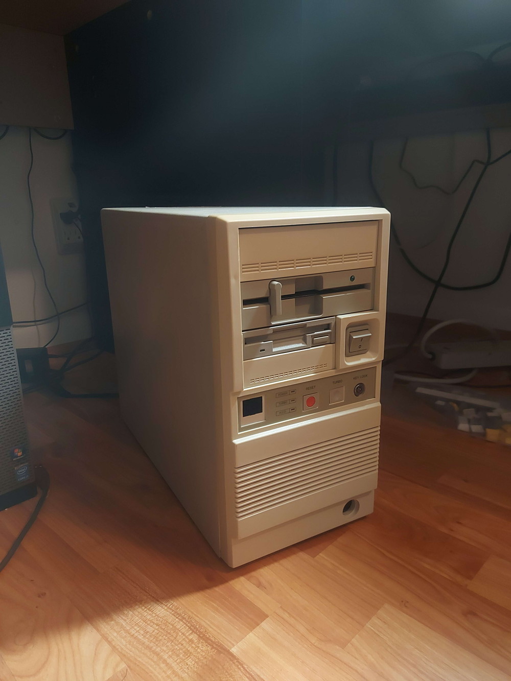
This is Camelia. She's a 386 PC I bought on ebay a few weeks back. The entire system seems to have initially been put together by an OEM called NCI. Every part inside had "NCI" warranty stickers and that badge in front seems to have a model name too (NCI Medalist 386).
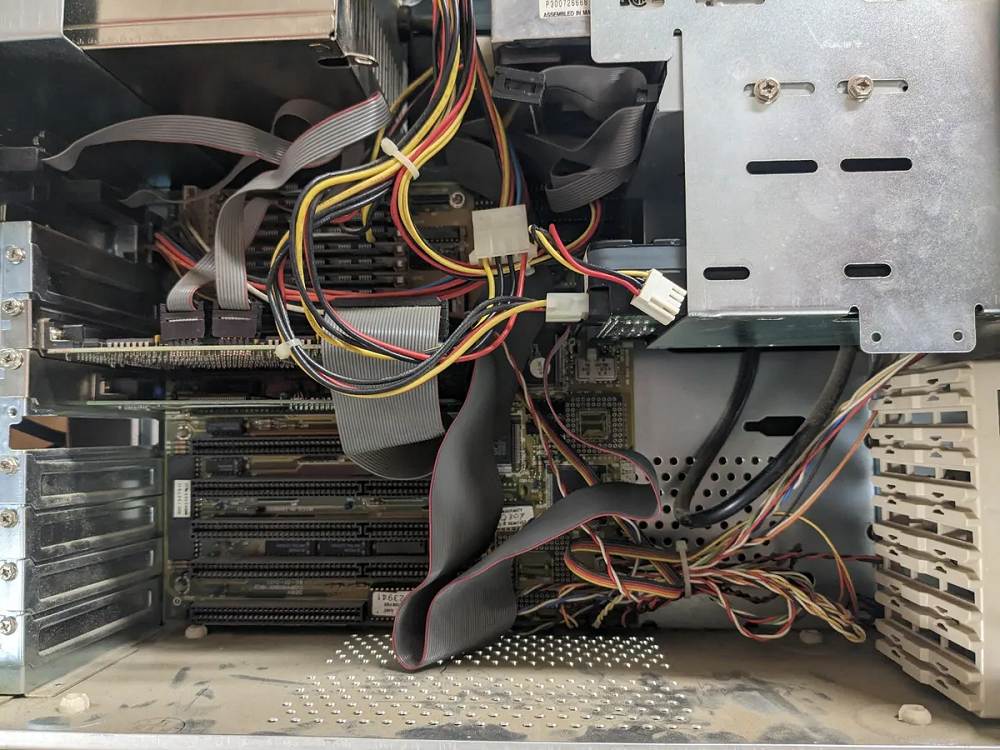
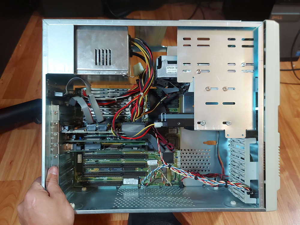
Everything has a sticker. 4 of the 8 RAM sticks, the 3.5", the 5.25", the motherboard, the PSU, the interface card, and even the VGA card. The only things that weren't original are, again 4 of the 8 RAM sticks, a Linksys Ether16 card in the 4th slot, and a Caviar 2700 with a pretty barebones DOS 6.22 install on it (at the time)
This is my first foray into retro x86 systems coming from MSX, so this whole world is new to me, so of course the machine I go for just happens to be ripe for potential upgrades and overclocking assuming everything goes right. First step was to strip her down, clean her up and get her put back together (the floppy drives were extra fun to get inside of).
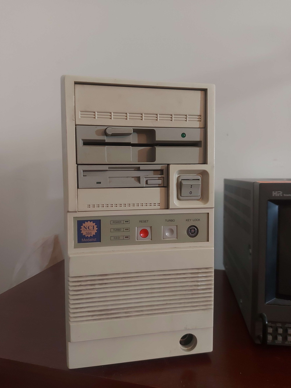
As soon as I got it out of the box:
Stripped down:
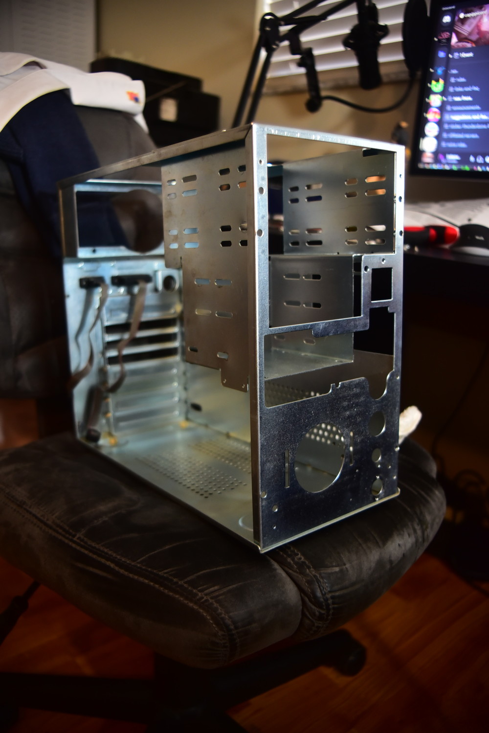
Fully cleaned:
Reassembled (I drilled out and retapped the case screw holes, all of them were empty but one):
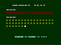
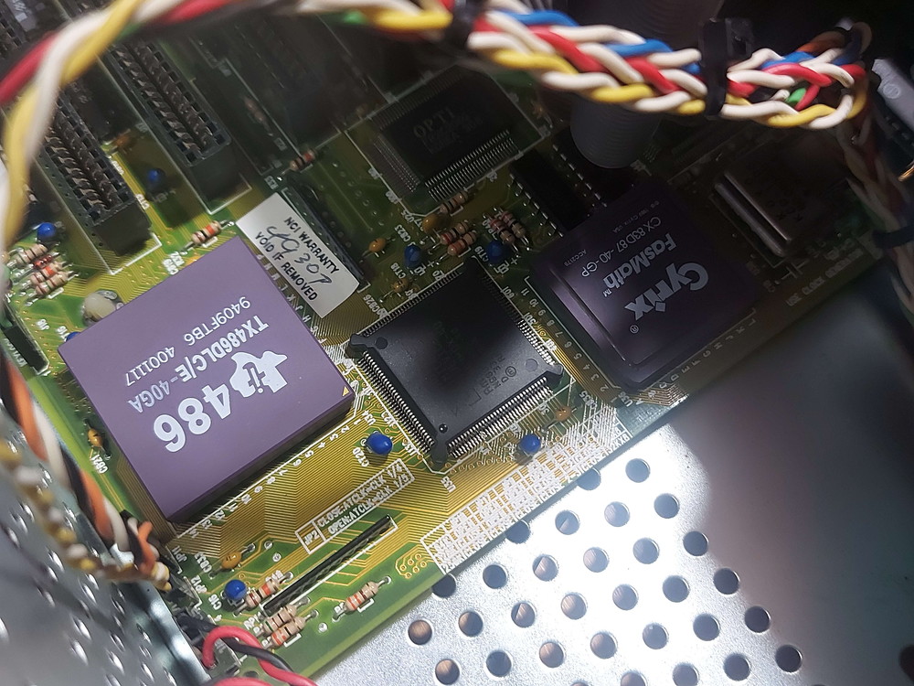
After a few days of troubleshooting and testing everything (since trying to dump the BIOS corrupted it and bricked the machine temporarily), I was finally confident enough in stability to put a Tx486DLC/E-40 and 40 MHz FasMath (black top) in.
With that little bit of backstory over, with a couple of little details sprinkled in, we can begin.
As you can imagine, this doesn't work immediately. This is where the fun starts.
This is my motherboard: https://theretroweb.com/motherboards/s/digicom-386h
https://stason.org/TULARC/pc/motherboards/U/U … D-486-386H.html
Seriously. Actually. The pictures are of my actual personal PCB.
The relevant place to look first is obviously the section labeled "CPU TYPE CONFIGURATION". This is where my problems are stemming from.
There seems to be very little documentation about this PCB and its other variants with different jumper positions/placements. Mine (the 386H) has virtually none. Until mine was submitted the chipset wasn't known, the manufacturer wasn't known, there was no BIOS dump (in a way there still isn't since mine was corrupted), and only the stason and RetroWeb jumper settings to go off of (we'll get to that).
Here are other boards that are nearly identical with some very important (imo) differences.
Taiwan Turbo Tec 386DX Cache
https://theretroweb.com/motherboards/s/taiwan … tec-386dx-cache
JUKO 386DX Writeback:
https://theretroweb.com/motherboards/s/juko-386dx-w-b
This one is the most interesting to me:
Magitronics A-B345G and -H
https://theretroweb.com/motherboards/s/magitr … a-b345g-a-b345h
(it has the full clock multiplier/selection circuit)
As you can see, none of them have the 3-pin J20 jumper, the documents for a few of them state that the location for jumper J1 is undocumented or unknown despite being in the silk screen markings (right next to the DLC socket and under the DX), and all of them having a J13 that's not present on my board.
That there was the first hurdle. The addition of jumper J13. Initial testing of the PCB revealed that DLC B12 (KEN#) is directly connected to AmDX 54 (FLT#). Initially not knowing how this pin worked I assumed that it was tied to the GND next to it and it was serving dual-purpose as both cache-enable and 386-disable. I was wrong about it, and it was a simple enough add. J13 ties KEN# and FLT# to GND.
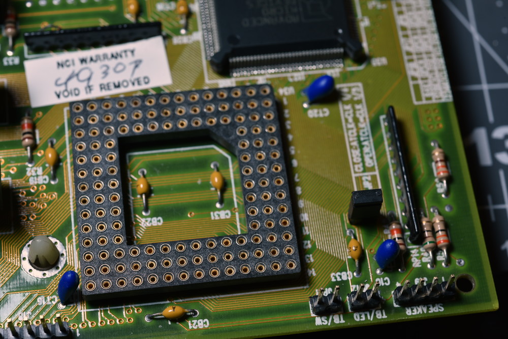
Note again that J13 and J1 are completely absent on the silk screen for my PCB. Cyrix support seems to be completely undocumented on the PCB itself.
After connecting the unlabeled J13 and attempting to boot the machine in its unique "documented" Cyrix configuration, where J5 (present on all variants) and J20 (present only on mine) are connected, I was met with a HIMEM error and told that the A20 gate could not be controlled.
This is extremely similar to the issues faced by Feipoa here.
However, none of the HIMEM switches here seem to work. I've also tried the other "compatible" /M: settings; 1, 11, 12, and 13. The machine loads HIMEM and then stops at [HIMEM is testing extended memory..._]
I'm stuck here. The PCB boots fine with the DLC in place, J5 closed, but J20 completely open. It doesn't seem as though the internal cache is working though, as no tests bring it up. The Cyrix tool (from Cyrix themselves, the blue-screen one) SAYS that the internal cache enable bit is set, but on its A20 screen says that Motherboard A20 is unmasked, Keyboard A20 is unmasked, and Fast A20 Gate is undetected despite being enabled in the BIOS (which I replaced). Internal Cache is also enabled in the BIOS (which I assume is setting the bit in the Config register).
BACK TO THE OTHER VARIANTS.
J1 is not undocumented. ALL variants of this board have its solder locations present. J1 connects the keyboard controller D1 pin to a pulldown resistor. What this does, I have no idea. Perhaps that 's why it was omitted from the Magitronics and Juko (which is populated with an SXL2-50 in one picture. J1 is obviously not necessary for Cyrix use.)
My board seems to function with J20 open, though I can't seem to get the cace to pop up. Turns out J20 might be so called because it's actually an A20 jumper. The middle pin goes to the DLC's A20M# pin. the other two pins connect A20M# to [1,2] ISA bus A20 through a 74F254 transceiver, or [2,3] DIRECTLY to the keyboard controller P21 output which seems to output the state of A20.
I have only tried running the PC with J20 set to (1,2) as the documentation states or completely open, which allows the PC to boot and HIMEM to start. It should be noted that no connection is made to the Am386DX, the state of J20 does not affect it at all. in fact it arrived to me with pins 1 and 2 connected. It's unlikely the previous owner did this and it was set from the factory.
The only possible outcomes in my mind are:
1. my board is very early and does not correctly support Cyrix chips, which is why it's totally unmarked
2. my board is very early and does not support Cyrix chips, so it was revised and the revisions are wrong still wrong (until you get to the JUKO which removes the requirement for JP1)
3. the documentation for J20 is "conceptually" backwards (it shouldn't be connected at all) and my board is somehow later (despite being 6 weeks older than the Magitronics according to the date stamps in the copper) and intentionally does not support Cyrix which is why the silk screen and JP13 (Am386 disable) was removed.
4. the documentation for J20 is electrically backwards and it should be pins [2,3] (KB A20) connected instead of pins [1,2] (74F245/ISA A20) (I have not attempted this)
5. The 74F245 is bad.
6. I've not enabled KEN# in the CPU config (its state is apparently ignored after reset and needs to be re-enabled manually. I have no idea how to do that automatically if this is the issue.)
7. The BIOS I replaced my corrupt BIOS with is missing features for 486DLC CPUs (this is the most unlikely scenario since it's pulled from another one of the other variants).
Should I keep trying? Should I give it up? Is it even possible to run Cyrix with cache on boards like this one if anyone else has a similar one? I suppose my one consolation is that even without cache a DLC40 is way faster than a DX40, and the interposer in this thread. would theoretically make an 80 MHz 386 machine possible (even without cache). I suppose another upside is that even if the project is toast I still have a complete setup and very attractive case (in my opinion) that I can put another motherboard in.
Thanks to any answers in advance.