VOGONS


HardMPU, anyone?

Topic actions

Reply 40 of 608, by ab0tj

User metadata
Rank Member
Rank
Member

I also have a 40Mhz oscillator. I ordered some 10 MHz crystals but then we'd be back to using the PLL. Either oscillator would give 100ppm worst case, so that will be well within 1%.

Reply 42 of 608, by ab0tj

User metadata
Rank Member
Rank
Member

Ok all, tell me what you think of this first schematic - the "Will it be fast enough edition" as I call it... Mostly what I'm not sure of is if I got the MIDI port pinout to match the Music Quest one found here: http://nerdlypleasures.blogspot.com/2010/03/t … land-mt-32.html - That diagram is somewhat confusing to me so I may have the pins transposed.

Fixed since this schematic: ISA 5V was connected to GND, MIDI optoisolator had pin 7 connected to 8. Also need to add some bypass caps.

Reply 43 of 608, by alexanrs

User metadata
Rank l33t
Rank
l33t

I prefered when glue logic was used for the status port - that way the PC would get the right status regardless of the firmware. Also the PIC now has to stop whatever it is doing and return the status. This might be fine, though, with a good firmware.

Oh, I'd never trust leaving TTL pins floating. You sort of can do it (floating TTL pins are seen as high in theory) but I'd not recommend it. Also, there is a possibility of just using an HCT gate instead of an LS one, and for CMOS floating pins are, by all mean, undefined. I'd just put some pullup resistors there.

Reply 44 of 608, by ab0tj

User metadata
Rank Member
Rank
Member
alexanrs wrote:

I prefered when glue logic was used for the status port - that way the PC would get the right status regardless of the firmware. Also the PIC now has to stop whatever it is doing and return the status. This might be fine, though, with a good firmware.

Oh, I'd never trust leaving TTL pins floating. You sort of can do it (floating TTL pins are seen as high in theory) but I'd not recommend it. Also, there is a possibility of just using an HCT gate instead of an LS one, and for CMOS floating pins are, by all mean, undefined. I'd just put some pullup resistors there.

As far as the status port goes, if the firmware leaves the status bits on the GPIO pins while the PIC is doing other things, the PIC doesn't really have to do anything when the status is polled. It would still get an interrupt, but it could exit the ISR as soon as it figured out it was a status read. Maybe it would be worthwhile to include a little bit of logic to keep the interrupt from even occurring in that case?

On the floating TTL pins, I see the open address jumpers and the extra gates in the 04 and the 08. I'll put some pull-ups there. Am I missing any others?

Reply 49 of 608, by ab0tj

User metadata
Rank Member
Rank
Member

So... It seems the PIC only executes one operation per 4 clock cycles. Meaning one operation per ISA bus cycle if I run it at 32 MHz. I doubt that will be quick enough to talk to the ISA bus even with 4 wait states, so it looks like I will be using latches and/or moving to AVR instead of PIC. AVR chips can do one operation per clock cycle, but only seem to be available up to 20 MHz in a DIP package.

Reply 50 of 608, by ab0tj

User metadata
Rank Member
Rank
Member

Ok, here's version 2... Much more complicated but should ease timing constraints considerably. It's obviously not done yet, this is really just the bus interface portion. It should basically have turned out like this: http://www.nomad.ee/micros/isapic.gif but with the addition of a third latch and flip-flop for writes to the control port. It also has reset logic to clear the flip-flops upon system reset. Can you guys check this for accuracy? Also, can you think of any easier way to handle the reset?

EDIT: Updated schematic.

Attachments

  • Capture.PNG
    Filename
    Capture.PNG
    File size
    76.24 KiB
    Views
    1533 views
    File license
    Fair use/fair dealing exception

Reply 51 of 608, by Jepael

User metadata
Rank Oldbie
Rank
Oldbie

Few things come to my mind.
-10K pull up R7 for opto pin is too high. Usually this would be between 200-1000 ohms. Just check other MIDI schematics.
-Opto pin 7 most likely should not be floating. Usually there should be a resistor to ground. I don't know what would be a good value for 6N135
-I have not seen 6N135 used for MIDI reception, have you? It could work, but at least you see 6N138 a lot, and resistor values are already figured out.

-I don't think the ISA bus can reset the PIC. It is not able to pull MCLR low if the diode is that way.

-I think you want to add some pull-up resistors in various places, as when the PIC is in reset (or no software loaded), it's pins are floating inputs (right?). This way it does not accidentally trigger some flip-flop.

-Original MPU401 when it is at address 0x300, it will respond to all addresses 0x300-0x307. See here: http://nerdlypleasures.blogspot.fi/2010/03/tu … land-mt-32.html. Not that it should be exactly compatible, but just for a reference.

-So it begins to look like the Music Quest card, minus the PAL.

Reply 52 of 608, by ab0tj

User metadata
Rank Member
Rank
Member
Jepael wrote:
Few things come to my mind. -10K pull up R7 for opto pin is too high. Usually this would be between 200-1000 ohms. Just check ot […]
Show full quote

Few things come to my mind.
-10K pull up R7 for opto pin is too high. Usually this would be between 200-1000 ohms. Just check other MIDI schematics.
-Opto pin 7 most likely should not be floating. Usually there should be a resistor to ground. I don't know what would be a good value for 6N135
-I have not seen 6N135 used for MIDI reception, have you? It could work, but at least you see 6N138 a lot, and resistor values are already figured out.

These are all good points. On the pullup, I had copied the resistor from another one in the schematic and neglected to change the value. Looks like a 6N136 (which I had intended to use but also didn't change the value) should have a 3.3k pullup. As far as pin 7 goes, I have seen more designs with it floating than not, but I will look into what a good value of resistor would be there as well.

Jepael wrote:

-I don't think the ISA bus can reset the PIC. It is not able to pull MCLR low if the diode is that way.

Wow. Looks like the reset circuit has many problems. The ISA reset line is active high, so I need to grab the signal for the OR gates on the other side of the inverter and either omit the diode or add a pulldown on MCLR. When using ISCP, VPP (MCLR) can be ~18V, so keeping the diode is probably wise.

Jepael wrote:

-I think you want to add some pull-up resistors in various places, as when the PIC is in reset (or no software loaded), it's pins are floating inputs (right?). This way it does not accidentally trigger some flip-flop.

Yes, that and the unused gates of IC8, IC9 and IC10.

Jepael wrote:

-Original MPU401 when it is at address 0x300, it will respond to all addresses 0x300-0x307. See here: http://nerdlypleasures.blogspot.fi/2010/03/tu … land-mt-32.html. Not that it should be exactly compatible, but just for a reference.

I think this one would do the same since A1 and A2 are ignored.

Jepael wrote:

-So it begins to look like the Music Quest card, minus the PAL.

Indeed. And if I were smart enough to move all that logic into a PAL, I would.

Reply 54 of 608, by ab0tj

User metadata
Rank Member
Rank
Member

Here's another I drew up, using an Atmega chip instead of PIC. This chip has 16k of ram and should run roughly twice as fast.

Attachments

  • Atmega.png
    Filename
    Atmega.png
    File size
    65.96 KiB
    Views
    1448 views
    File license
    Fair use/fair dealing exception

Reply 55 of 608, by ab0tj

User metadata
Rank Member
Rank
Member

I think I like the AVR chip since they seem to be more supported these days. I realized I do have an ISP programmer for these chips, so I will be going with that design unless anyone has a compelling reason not to. Plus, the extra speed and RAM will be nice to have.

I guess since this project seems to be moving forward, it's time to decide on a name. Possibilities I have thought of are AVR-401 (for the Atmel chip), VG-401 (Vogons namesake), Clone401, or just stick with HardMPU (if bjt is OK with that). Any input?

Reply 56 of 608, by Jepael

User metadata
Rank Oldbie
Rank
Oldbie

I think I have an ISP for these as well. Used to write stuff with WinAVR package for several ATMegas.
I can also help with debugging and writing software, all I need is PCB and preferably the parts as well so I can solder them on. I only have to learn how to develop for AVR in Linux these days.

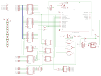
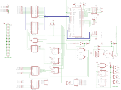
I see the MIDI receive is on different uart than MIDI transmit, that's nice, so they are separate. May I suggest adding the other RXD/TXD pins to a pin header to debug the card with a TTL serial port? Although, then both uarts need to run at 31250 BPS, but fortunately modern USB serial ports can handle it. Maybe if MIDI TXD/RXD used one uart at 31250, so you could use other uart at like 250 kilobaud for debugging? Also you can never have enough debug leds, buttons, jumpers, dip switches and test points on prototypes. All extra pins and few ground pins to some pin header maybe, for logic analyzer?

As the AVR supports a bootloader, maybe the ISA or MIDI interface could be used to reflash the firmware? Or maybe even bring the ISP wires to unused pins of D9.

Regarding the name, I like something-401 but not AVR-401 much. Just because it has an AVR do perform its stuff, it could be anything other than AVR. Maybe xxx-401-AVR if necessary if someone makes other versions with other MCUs, or replaces the glue logic with CPLD. VG-401-AVR? VoGon Midi VGM-401? Vogon Midi Processor VMP-401? HardMPU is also nice.

I also have some words running around my head like Intelligent or Emulator, like Intelligent Midi Processor (IMP) or Intelligent Midi Emulator (IME). Intelligent Midi Clone, but then again, what would it clone..

Reply 57 of 608, by ab0tj

User metadata
Rank Member
Rank
Member

Actually, the TX and RX were and error on my part (see the updated schematic above). I can't think of any huge advantages to having them on separate UARTs. And I did route the other one out to a pin header 😀 I'm also working on redoing the schematic yet again to use JTAG instead of ISP so it can do in-circuit debugging. I'm going to have to make a new schematic once I get things all figured out, this one is getting quite messy.

Thanks for the offer on debugging and software writing, I may have to take you up on that. The proof-of-concept board will just be an ISA prototyping board, though. I'll have to get some actual PCBs made up once things are a little more solidified.

As far as the name goes, I like IMP (Intelligent Midi Processor), or HardMPU.

Reply 58 of 608, by ab0tj

User metadata
Rank Member
Rank
Member

Possibly overkill, but this one has both JTAG and ISP for programming a debugging options.

Attachments

  • Atmega.png
    Filename
    Atmega.png
    File size
    68.41 KiB
    Views
    1429 views
    File license
    Fair use/fair dealing exception

Reply 59 of 608, by ab0tj

User metadata
Rank Member
Rank
Member

Ok, some minor revisions based on some more reading of the MPU manuals. Basically it ended up being what Jepael was trying to tell me all along 😀

I think this will be the final version of the schematic unless someone finds something wrong with this one. Parts arrive today so I can start laying it out on a breadboard for testing. I also have some AVR C code written up that should be able to do UART mode. It is basically just a polling loop that checks the status of the various input ports and funnels the bytes to the appropriate output ports. Once that is working well, I will start on implementing intelligent mode.

Attachments

  • Atmega.png
    Filename
    Atmega.png
    File size
    65.96 KiB
    Views
    1381 views
    File license
    Fair use/fair dealing exception