VOGONS


Reply 120 of 844, by Robert B

User metadata
Rank Oldbie
Rank
Oldbie

Today was one of those GLORIOUS DAYS!!!

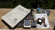
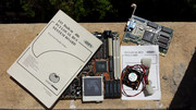
Around 9.30 in the morning, I left home and went to the place were I keep my old hardware.

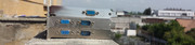
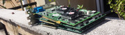
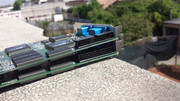
I'm feeling great and the weather is just right for what I need to do. Mostly sunny, a litte windy and sometimes a little cloudy. I'm all alone in the building and nobody is there to make me miss my TARGET: the cleaning of all the remainig hardware I aquired lately.

I already know what I want to do and everything goes according to plan.

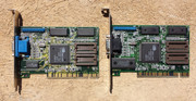
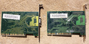
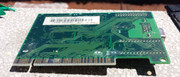
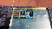
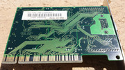
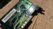
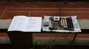
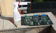
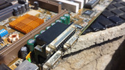
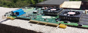
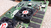
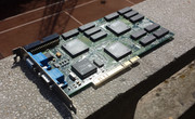
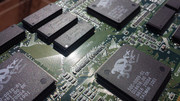
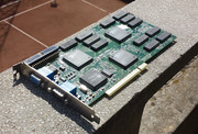
I set up the workplace and I start with the MAXX and the V2 SLI.

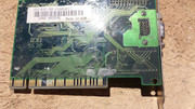
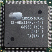
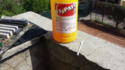
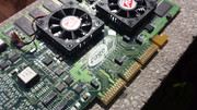
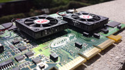
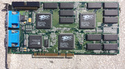
The MAXX received an injection with isopropyl alcohol 99% to remove the dirt from under one of the graphic chips.A lot of dirt still comes out. The V2 SLI cleans up really well and doesnt pose any additiona troubles. The ORAFOL STONE GUARD FILM again protects the stamped ink markings.

gallery: https://postimg.cc/gallery/3f0ndiuh8/

clean-1.jpg clean-2.jpg clean-3.jpg

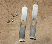
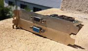
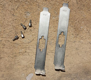
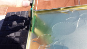
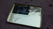
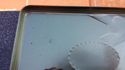
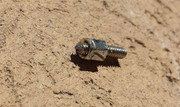
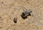
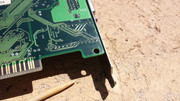
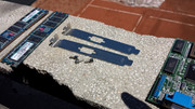
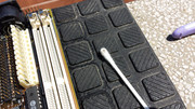
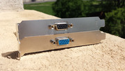
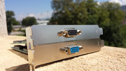
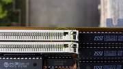
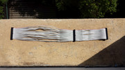
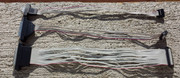
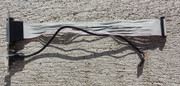
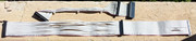
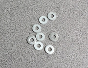
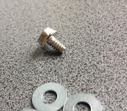
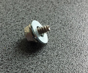
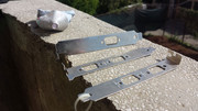
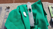
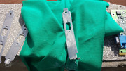
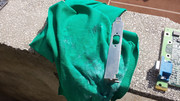
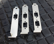
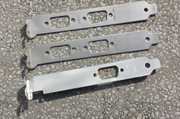
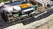
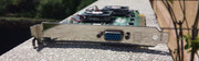
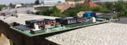
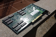
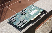
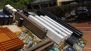
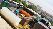
While the graphic cards dry in the sun I turn my attention to the brackets. They have lost their shine and are covered in a hazy deposit which is very hard to clean. I take the decision to not buff them with a felt wheel and instead use an abrazive paste and a soft rag. The choice is the right one and the results are past my expectations. The bracket of the MAXX is like a mirror in minutes. The brackets from the V2 SLI are hazy from factory but they also clean up well. I also clean with abrazive paste the fixing screws until they shine. Aferwards I washed all the bracket and screws with isopropyl alcohol 99% to remove all the leftover paste.

See the results bellow!

gallery: https://postimg.cc/gallery/1d9cqrb9o/

pasta-1.jpg pasta-2.jpg pasta-3.jpg pasta-4.jpg pasta-5.jpg pasta-6.jpg pasta-7.jpg pasta-8.jpg pasta-9.jpg pasta-10.jpg pasta-11.jpg pasta-13.jpg

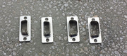
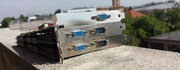
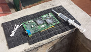
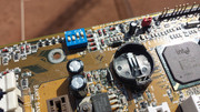
Once I dealed with the above problems I addressed the problem of rust. MY No 1 ENEMY!!!

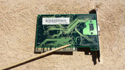
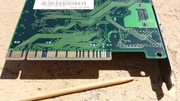
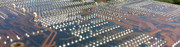
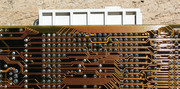
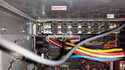
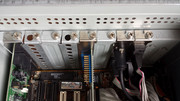
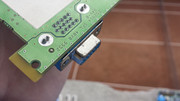
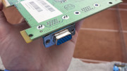
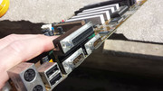
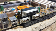
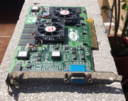
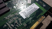
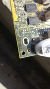
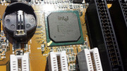
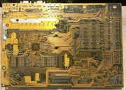
I used a cotton stick dipped in an auto rust remover solution. I took great care not to use too much as it is corrosive. The VGA port of the MAXX cleaned up really well. In the case of the Gigabyte 6BXC I had to remove the fixing screws from all the ports and then use the solution. Even so the rust is very hard to remove. I had to use fine grit sandpaper to remove all of it. Then I used a cotton stick with abrazive paste to give the metal some of its initial shine. Then I used isopropyl alcohol 99% to wash all the parts to remove the rust remover solution and the abrazive paste. Everything goes without a hitch.

gallery: https://postimg.cc/gallery/1ro9rxo5w/

rust-0.jpg rust-1.jpg rust-2.jpg rust-3.jpg rust-4.jpg rust-5.jpg rust-6.jpg rust-7.jpg rust-8.jpg rust-9.jpg

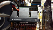
Next came the assembly of the graphic cards and I put back the screws I took out from the Gigabyte 6BXC motherboard.
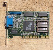
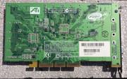
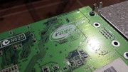
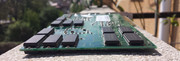
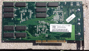
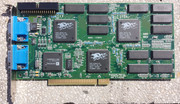
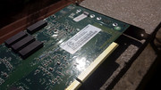
Ati Rage Fury MAXX

gallery: https://postimg.cc/gallery/vwaubj6i/

maxx-cln-1.jpg maxx-cln-2.jpg maxx-cln-3.jpg maxx-cln-4.jpg maxx-cln-5.jpg maxx-cln-6.jpg maxx-cln-7.jpg maxx-cln-8.jpg maxx-cln-9.jpg maxx-cln-10.jpg maxx-cln-11.jpg maxx-cln-12.jpg maxx-cln-13.jpg maxx-cln-14.jpg

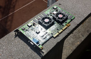
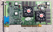
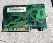
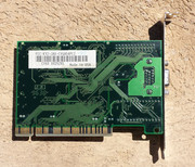
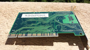
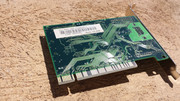
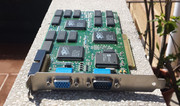
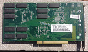
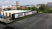
2x 3dfx VooDoo 2 Creative CT 6670

gallery: https://postimg.cc/gallery/mivytcry/

voodoo2-cln-1.jpg voodoo2-cln-2.jpg voodoo2-cln-3.jpg voodoo2-cln-4.jpg voodoo2-cln-5.jpg voodoo2-cln-6.jpg voodoo2-cln-7.jpg voodoo2-cln-8.jpg voodoo2-cln-9.jpg voodoo2-cln-10.jpg voodoo2-cln-11.jpg voodoo2-cln-12.jpg voodoo2-cln-13.jpg voodoo2-cln-14.jpg voodoo2-cln-15.jpg voodoo2-cln-16.jpg

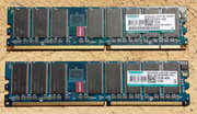
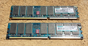
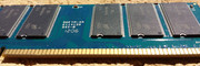
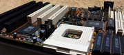
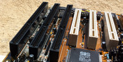
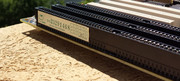
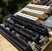
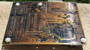
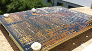
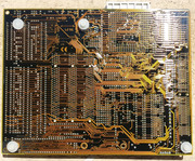
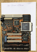
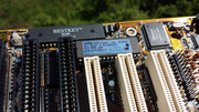
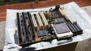
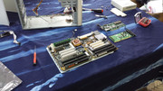
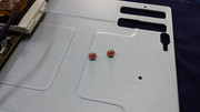
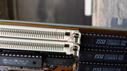
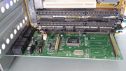
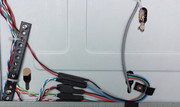
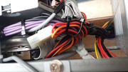
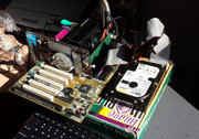
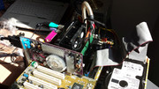
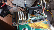
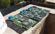
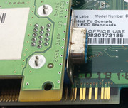
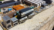
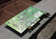
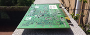
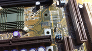
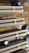
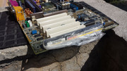
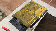
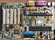
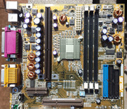
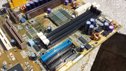
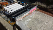
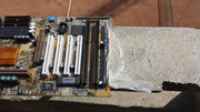
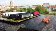
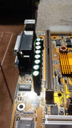
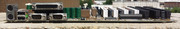
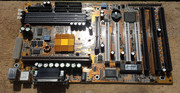
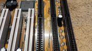
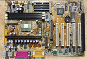
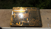
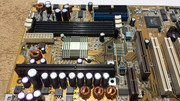
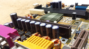
The Asus K7M and Gigabyte 6BXC motherboards were prepared for the wash. I applied ORAFOL STONE GUARD FILM over the stamped ink markings. I also used a plastic bag to cover the ISA slots to protect the paper labels. The improvisation with the plastic bags and rubber bands doesnt work as I intended becasue the alcohol gets into the slot from beneath. Even so the paper labels survive despite beeing soaked. The bag protected the labels beeing contaminated by all the dirt removed by the alcohol.

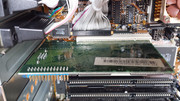
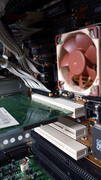
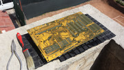
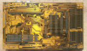
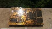
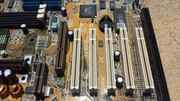
Both of the motherboards came out GOLDEN!!!
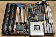
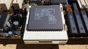
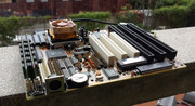
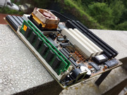
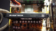
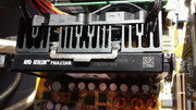
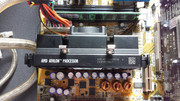
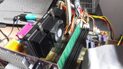
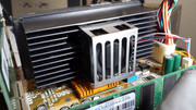
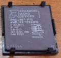
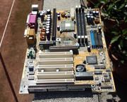
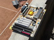
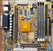
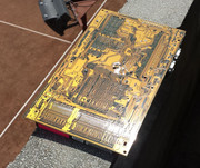
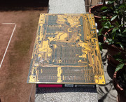
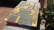
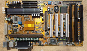
Asus K7M v1.04

gallery: https://postimg.cc/gallery/iatdnk2m/
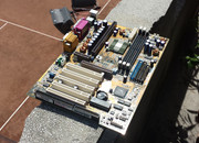
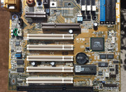
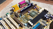
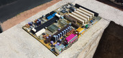
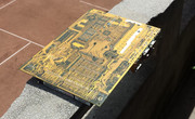
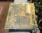
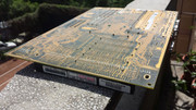
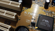
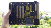
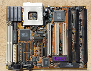
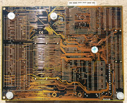
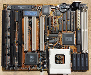
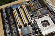
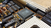
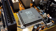
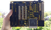
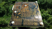
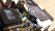
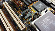
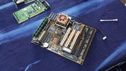
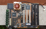
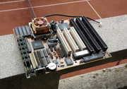
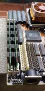
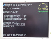
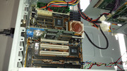
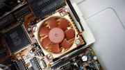
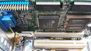
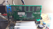
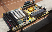
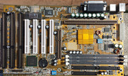
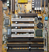
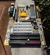
k7m-cln-1.jpg k7m-cln-2.jpg k7m-cln-3.jpg k7m-cln-4.jpg k7m-cln-5.jpg k7m-cln-6.jpg k7m-cln-7.jpg k7m-cln-8.jpg k7m-cln-9.jpg k7m-cln-10.jpg k7m-cln-11.jpg k7m-cln-12.jpg k7m-cln-13.jpg k7m-cln-14.jpg k7m-cln-15.jpg k7m-cln-16.jpg k7m-cln-17.jpg k7m-cln-18.jpg k7m-cln-19.jpg k7m-cln-20.jpg k7m-cln-21.jpg k7m-cln-22.jpg k7m-cln-23.jpg

Gigabyte 6BXC v1.7

gallery: https://postimg.cc/gallery/3gawa7edw/

6bxc-cln-1.jpg 6bxc-cln-2.jpg 6bxc-cln-3.jpg 6bxc-cln-4.jpg 6bxc-cln-5.jpg 6bxc-cln-6.jpg 6bxc-cln-7.jpg 6bxc-cln-8.jpg 6bxc-cln-9.jpg 6bxc-cln-10.jpg 6bxc-cln-11.jpg 6bxc-cln-12.jpg 6bxc-cln-13.jpg 6bxc-cln-14.jpg 6bxc-cln-15.jpg 6bxc-cln-16.jpg 6bxc-cln-17.jpg 6bxc-cln-18.jpg 6bxc-cln-19.jpg 6bxc-cln-20.jpg 6bxc-cln-21.jpg

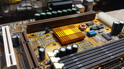
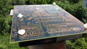
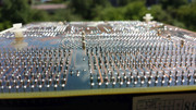
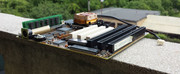
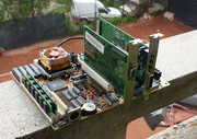
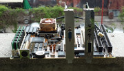
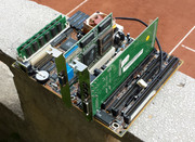
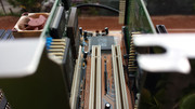
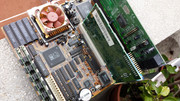
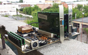
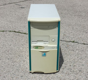
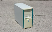
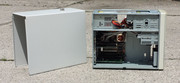
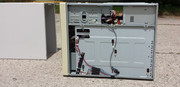
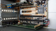
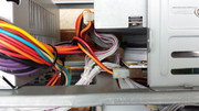
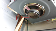
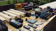
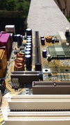
Now for your viewing pleasure some GLAMOUR PICTURES!!!

gallery: https://postimg.cc/gallery/102jz0axw/

6bxc-glamour-1.jpg 6bxc-glamour-2.jpg 6bxc-glamour-3.jpg 6bxc-glamour-4.jpg 6bxc-glamour-5.jpg k7m-glamour-1.jpg k7m-glamour-2.jpg k7m-glamour-3.jpg k7m-glamour-4.jpg k7m-glamour-5.jpg k7m-glamour-6.jpg on-top-1.jpg on-top-2.jpg

It's 13.20 and in less than 4 hours I gave back the shine to these "sacred monsters" of times passed by.

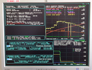
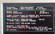
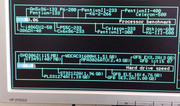
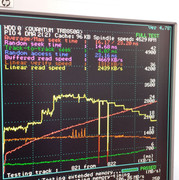
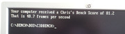
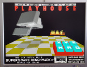
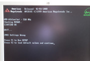
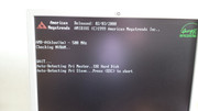
Next will be a software testing session but this will have to wait a while.

More later.

Last edited by Robert B on 2018-04-18, 20:04. Edited 1 time in total.

Reply 122 of 844, by Robert B

User metadata
Rank Oldbie
Rank
Oldbie

I'm glad you like my posts 😁

@AzzKickr - I check the pics regularly and usually they are available. I even make random tests and all the images are available. Maybe you cand point the images with problems. Thanks.

Now postimage.org has some problems or it is down.It was a PITA to upload the latest images.

I would upload them to vogons but I was afraid about the size of the uploads and I thought that somebody might take them down. I say that all the pics are about 5-6 gigs.I dont know if I am allowed to post them on vogons. If I can, maybe somebody will give me some hints.

If by chance I see that some pictures arent available I'll find another solution. You can be sure of that 😀

Reply 123 of 844, by Robert B

User metadata
Rank Oldbie
Rank
Oldbie

I managed to find the missing piece of the 5x86 puzzle 😀 My first motherboard! Zida Tomato Board 4DPS 2.11 - plus some extras 😁.

Now I'll have the motherboard+cpu+cooler+ram+hdd+vga+ODD+case = MY QUEST which started over two years ago IS COMPLETED!!!! 😀

Actually the 5x86 started all this "madness" 😁

Full story later this week!

L.E. Yesterday an today I made a full backup to the stuff I posted here and other sites. All pages have been transformed in pdf with web2pdf and all the pictures have been stored in an organzied fashion 😁 .To my surprise they dont occupy so much space 😀 2085 images - 1.34 GB. Total pictures taken before editing ~ 14GB

With these measures I can revive the thread anytime !

Reply 125 of 844, by Robert B

User metadata
Rank Oldbie
Rank
Oldbie

The search for my first computer is over. Now I have all the pieces of the puzzle and I can pursue other objectives

I hope, you didnt think, even for a fleeting moment, that I am going to stop . At the very least I'll take it a little bit slower...😁

Today I received the single most important piece of hardware, which I needed to complete the recreation of my 1st PC.

BEHOLD THE HOLY MOTHERBOARD, the socketed mother in which ALL THE OTHER PARTS dig in their PINS and come to life.

The package was delivered by courier in the morning around 09.55 The box was smaller than usual. After receiveing ATX boards, V2 SLI's and other bigger components, the board which I was about to receive was only 220mm x 170mm, smaller than a A4 sheet of paper - https://postimg.cc/image/l57zt3w3v/

Surprisingly, I was very calm the day before, because I knew what I was about to receive. I went to bed thinking about the Tomato Board/Zida 4DPS. I knew its layout, I knew all her curves and I knew that tomorrow I'll have it in my hands 😁

So today after 21 years I have in my possession the motherboard of my first PC. This was my ticket into this realm and it was AWESOME! This was the single most important piece I needed it and NOW IT'S MINE!

Also I purchased two Cirrus Logic 5446 PCI 1MB video cards. I remember I used to install the CL 54xx drivers in Win 95 but I'm not sure if it the video adapter was 5430 or better. This mistery will be solved only if I find the original invoice from 1996. I know I have it but it's burried deep in a big closet at my workplace.

An AMD 5x86 P75 - 133MHz - ADZ and a socket 3 cooler completed this purchase.

Now I have all the pieces needed to recreate my first PC: motherboard, cpu, odd, hdd, case, soundcard, etc. Initially I wanted to rebuild the 5x86 build with this motherboard but I guess for now I'll keep it close so I can see it for several days/weeks 😁

From my first PC there are only two surviving pieces: the soundcard and the motherboard manuals.

The only thing that stood out like a sore thumb was the almost identical 2x1GB DDR 400 Kingmax kit I bought for the socket A platform, after I had troubles with the PQI memory.

Arrival state

gallery: https://postimg.cc/gallery/21311om3a/

CL-drt-1.jpg CL-drt-2.jpg CL-drt-3.jpg CL-drt-4.jpg cooler-drt-1.jpg cooler-drt-2.jpg Kingmax-drt-1.jpg Kingmax-drt-2.jpg zida-drt-1.jpg zida-drt-2.jpg

Cleanup

The motherboard was clean by some standards and some may say VERY CLEAN, but after seeing some light dust on the ISA slots and a cotton stick dipped into isopropyl alcohol 99% yielded black marks I prepared the motherboard for a bath.

I took off a small round sticker form the back to avoid damage.

The wash went well. The only "problem" was that after the wash with isopropyl alcohol 99% the purple tint from the BIOS hologram sticker kind of vanished, now it's a nice cool SILVER tint.If I knew this I would've protected the hologram with ORAFOL STONEGUARD FILM like I did to the V2's, K7M and 6BXC. Live and learn. The Pentium II cartridge holograms werent affected by isopropyl alcohol.

Piece of advice: if you want to preserve the paper labels, stamped ink markings and some hologram, first make a test with a cotton stick dipped into isopropyl alcohol 99% and then wash the entire component. Use a film to protect the stamped ink markings.

While the motherboard was drying I took it in my hand and accidentaly bent a little, the MOSFET near the CPU socket. I straightened it and I took off the heatsink to see if it was damaged. The GOOD NEWS WAS: NO DAMAGE! HuH!!! That was a close one! 😁

I also saw a scratch on the opposite side of the adjacent capacitor. The scratch isnt very big and it wasnt made by me. No biggie here 😀

The video cards were more dirty than the motherboard. One in particular (the one with the black connector) had a crust with a white-greenish colour. It was very hard to remove.

First I took off the brackets and polished them by hand with abrasive paste. They came out nice.

One screw that holds the bracket had a sheared screw from the VGA cable plug. For the sake of authenticity I took the decission to remove the sheared piece. A vice, a screwdriver and a small hammer = problem solved. The fixing screws were scratched when I received the video card. Also the black VGA connector was slighlty bent, sign that the sheared screw took some force until it broke.

I removed a little rust from the VGA connector.

The white-greenish deposit from the video card wasnt removed by an isopropyl spray so I had to improvise. I took a metal cap from a box and put some isopropyl alcohol just enough that the backside of the card was always dipped/wet. I checked the card regularly and it stayed there 30 min - 1 hour. Every so often I used cotton sticks dipped in alcohol to remove the deposit and the hard stuff was scraped off with a small bamboo stick. In the end I managed to restore the appearance of the card.

Based on these findings
I can say that if you have a very dirty component you can submerge it in an alcohol bath. I dont know the submerging time or if this porcedure will damage the laquer or other components. Trial and error. Also in this way you lose much more alcohol due to evaporation. The remaining alcohol should be discarded as it is already contaminated. YMMV.

The cooler looked CLEAN but LOOKS can be DECEVING!!!!

The Kingmax RAM received a wash too. For good measure 😀

gallery: https://postimg.cc/gallery/o1z22npk/

Cl-cln-1.jpg Cl-cln-2.jpg Cl-cln-3.jpg Cl-cln-4.jpg Cl-cln-5.jpg Cl-cln-6.jpg Cl-cln-7.jpg Cl-cln-8.jpg Cl-cln-9.jpg Cl-cln-10.0.jpg Cl-cln-10.1.jpg Cl-cln-10.2.jpg Cl-cln-10.3.jpg Cl-cln-11.jpg Cl-cln-12.jpg Cln-1.jpg Cooler-cln-1.jpg Cooler-cln-2.jpg Cooler-cln-3.jpg Zida-cln-1.jpg

For this cleaning operation I used about 350 ml of isopropyl alcohol. I sure wasnt stingy 😁 believe me!!!

isopropylalc99.jpg

Finished results!!!

Allocated time ~ 2 ore

Nothing more to report....just enjoy!

gallery: https://postimg.cc/gallery/1kk3gw6l8/

cl-1-0.jpg cl-1-1.jpg cl-1-2.jpg cl-1-3.jpg cl-2-0.jpg cl-2-1.jpg cl-2-2.jpg cl-2-3.jpg cl-grp-1.jpg cl-grp-2.jpg Cooler-1.jpg Cooler-2.jpg Cooler-3.jpg Cooler-4.jpg kingmax-1.jpg kingmax-2.jpg kingmax-3.jpg kingmax-4.jpg kingmax-5.jpg

zida-1.jpg zida-2.jpg zida-3.jpg zida-4.jpg zida-5.jpg zida-6.jpg zida-7.jpg zida-8.jpg zida-9.jpg zida-10.jpg zida-11.jpg zida-12.jpg zida-13.jpg zida-14.jpg zida-15.jpg zida-16.jpg zida-17.jpg zida-18.jpg zida-19.jpg zida-20.jpgzida-21.jpg zida-22.jpg zida-23.jpggroup-1.jpg group-2.jpg

More later.

L.E. It seems one of the Kingmax DDR 400 modules is missing a contact pad....RIP!!!

DAMAGE.jpg20325944_640x480_1444165990.jpg 1430303742411_big.jpg

Last edited by Robert B on 2018-04-18, 20:05. Edited 1 time in total.

Reply 127 of 844, by Robert B

User metadata
Rank Oldbie
Rank
Oldbie

5x86 - THE REBIRTH

Ladies and gentlemen, I present to you MY FIRST PC!

Almost two years ago I embarked on a journey to find and rebuild my first personal computer.

This was no easy task, as the components I wanted, were getting scarce by the second and many have already been turned to scrap. Somehow I managed to find the hdd, the soundcard (by a twist of fate my original one 😀) and the case. I was missing the motherboard, the odd and the video adapter. These were replaced with the closest equivalent I could find: a SiS 496/497 motherboard, an Ark Logic ARK2000PV video adapter and a 52X CD-ROM.

The assembly of this system made me remember all the good times I had back in '96, when my first PC was standing in my room, happily doing his tasks and having the divine new electronics smell 😁 GOOD TIMES!!!

The 5x86 build was the first one posted on this thread.

During all this time I searched for my missing pieces of the 5x86 puzzle. I managed to find my missing CD-ROM, a Goldstar/LG CRD-8160B. This one didnt have the front panel headphone jack and had a different bezel but for me, the most important thing was the model number CRD-8160B. This unit was cleaned, tested and ready to be put to work. Details in the posts above.

The motherboard proved to be the most illusive. No matter were I looked I couldn't find it. I didnt lose hope but I was pretty close to. All this time the string 4DPS 496/497, P75....133MHz, was daunting me......damn, I dont think I'll ever get to see one in the FLESH!!!

By a twist of fate, 10 days ago I received a small package containing my last two missing pieces of the 5x86 puzzle: the ZIDA/TOMATO 4DPS SiS 497/497 motherboard and the Cirrus Logic 5446 8260B/V6. Back in the day I think I had a Cirrus Logic 5430 but this 5446 is as close as it gets. The 5446 received a 1MB video memory upgrade just because it could 😁. Against its will, a SiS video adapter was left without its memory chips.All for the greater GOOD!!! 😀 These last pieces were found on the local OLX site.

So here I was with all the pieces of the 5x86 puzzle and I was ready to do the right thing and recreate MY FIRST PC!!!

Today I had three free hours and I put them to good use.

The first task was to decide which CPU I was going to use. I had two revisions of the AMD 5x86 CPU: ADW and ADZ. The ADZ was more desirable as it could run without a heatsink and a fan. I stood a moment and said to myself that back in the day I really couldnt have the ADZ as it was uncommon and I went with the ADW.

I removed the labels from the back of the CPU. I really hate those stickers, removing them is always a PAIN IN THE A$$. Thank GOD FOR ISOPROPYL ALCOHOL 99%!!!

Then I set up the jumpers, which by the way didnt need setting as it seems the motherboard used to run the same CPU model 😁 Go figure!

Taking apart the original 5x86 build, filled me with mixed emotions as I thought it'll never be disassembled again. Regardless, I marched on and did what I had to do. An easy and quick task.

gallery: https://postimg.cc/gallery/e9gq5f5m/

prep-1.jpg prep-2.jpg prep-3.jpg prep-4.jpg prep-5.jpg prep-6.jpg

Next, I attached the heatsink and made a mock-up to see how my system will look like.

LOOKING GOOD YOU sexy piece of HW Pr0n!!! 😁

gallery: https://postimg.cc/gallery/xb9fff6s/

S-1.jpg S-2.jpg S-3.jpg S-4.jpg S-5.jpg S-6.jpg S-7.jpg S-8.jpg S-9.jpg S-10.jpg S-11.jpg S-12.jpg

Now came the time to get the motherboard in the case. This proved more challeging that I anticipated.

Of course the fixing holes from the motherboard tray didnt lign up with the new motherboard so I did what I had to do, and I added two new standoffs.

The 4DPS motherboard is so compact that in one corner I couldnt insert a fixing screw as it would damage a nearing IC so I had to improvise. I remembered that back in the day you had a screw in plastic standoff. GOOD LUCK FINDING THOSE TODAY. So I took a regular plastic standoff, used a grinding wheel to remove as much as I could from its collar, then I cut all the remaining bits and screwd the thing in the motherboard tray. PROBLEM SOLVED!!! 😁

When I tried to insert the tray and motherboard combo in the case, a metal bar used to strengthen the case , stood in my way. I took out the top RAM stick and put the tray in, then I tried to insert the RAM stick back in. NO DICE. I removed the power supply and tried again. NO DICE.

Hmmmm....I took out the tray and started to look at it with a blank expression. What to do? To my surprise I find a problem with a RAM slot as I see a bent pin. SHEEETTTT!!! Not good. With great care I straightened the pin and the crysis was averted. HUH!!! That was a close one. I started looking at the pictures with the motherboard, I took when I cleaned it and I'm 90% sure it came with the bent pin. I dont have a clear picture but in one picture I took you can see the bent pin. Regardless the problem was solved.

I put back all the RAM sticks, loosened the power supply from its fixing screws, then I lifted with a hand the metal bar and with the other I inserted the tray. THE MOTHERBOARD IS IN!!!

Observe how close to each other the RAM stick are and the small clearance they have until they touch the case. You can be sure I took great care and there is no danger of the motheboard or the RAM sticks to come in contact with the case.

Inserting the power supply connectors proved challenging too. The fit is extremely TIGHT as the securing clips must slide between three resistors. YEP BOYS I think this one's a V....N!!! 😁 In the end the connectors went ALL THE WAY IN!!! 😁

HUH!!!

gallery: https://postimg.cc/gallery/x6knmut4/

Assembly-1.jpg Assembly-2.jpg Assembly-3.jpg Assembly-4.jpg Assembly-5.jpg Assembly-6.jpg Assembly-7.jpg Assembly-8.jpg Assembly-9.jpg Assembly-10.jpg

After these tasks I decided to make a BOOT test and attached all the front panel connectors.

The system came to life on the first powerup and it made a clear and happy: beep! I'm allive! 😀 The CL5446 and the 4DPS are in excellent working condition! No drama, no more problems!

The PC is purring like a kitten, the hdd makes all the right noises and the Noctua fan is silent as a wisper. EPIC WIN 4 ME!!!

gallery: https://postimg.cc/gallery/1lk67mme4/

1stboot-1.jpg 1stboot-2.jpg

REMEMBER MY FACE!!! SAY MY NAME!!! 😁

Results-1.jpg

Next: wire management & software testing.

More later.

Last edited by Robert B on 2018-04-18, 20:06. Edited 1 time in total.

Reply 128 of 844, by Robert B

User metadata
Rank Oldbie
Rank
Oldbie

For the 5x86 wire management session I TOOK NO PRISONERS 😁

Spaghetti anyone?

Work In Progress!!! 😁

Story tonight! 😁

Attachments

  • boot-1.jpg
    Filename
    boot-1.jpg
    File size
    615.7 KiB
    Views
    1629 views
    File license
    Fair use/fair dealing exception
  • WM - 1.jpg
    Filename
    WM - 1.jpg
    File size
    122.88 KiB
    Views
    1629 views
    File license
    Fair use/fair dealing exception

Reply 129 of 844, by Robert B

User metadata
Rank Oldbie
Rank
Oldbie

With what should I start? Hmm....this story doesnt have so much material going for it but I'm sure I can make SOMETHING SPECIAL with it! 😁

Saturday the AGER case received all of its "organs" and she almost went into cardiac arrest with all its 133MHz!!!

Next task on the LIST: WIRE MANAGEMENT!!!

I took out the FDD and 40 pin ATA cables and I did a quick test to see how they look. I really didnt like the results. Last time I rolled them up and they ended up like a GIANT FUNNEL. NOT GOOD!!!. I tried to let them be and hang like in the GOOD OLD DAYS but they looked HORRIBLE!!!

What to do? CLICK! I have an idea!

One or two years ago I saw somebody fold ribbon cables in half, then in another half, across their length and then tied them up with zip ties. I tried to do the same but the cables turned to be STIFF AS A BOARD!!! GOD DAMN IT!!!

You know what came next? 😁 EXTREME MEASURES of course.

I started by looking on the internet for some information about separating ribbon cable in individual strands / groups of wires. I found something, but as usual what I want is hard or can't be done....

I remember the 80 pin round ATA cables with their individual wires.

So I take in my hand a cutter / X-acto knife with a fine blade and I CUT THE FLESH!!! Curiously no blood comes out! Hi Hi Hi! (evil smile)

And a TUTORIAL IS BORN!

ATA / IDE / FDD RIBBON cable - MANAGEMENT or WIRE MANAGEMENT OF RIBBON CABLES IN AT PC CASES - 386/486/586 etc

Steps:

STEP 1. You take the ribbon cable you wish to separate in groups of wires. You cand choose 2,4,6,8 etc, 3,6,9 etc or any number of wires you want to group. I went straight to the NUMBER 2 for the FDD and ATA ribbon cables, after I found out that groups 10 wires arent very flexible. You can experiment as much as you like.

STEP 2. Place the ribbon cable on a glass surface with a source of light underneath. In my case I placed it against a glass window.

NOTE. First choose the cable with the most visible / bigger space between wires by placing it against a source of light. You'll see that not all cables are the same.

cable-1.jpg

PROS and CONS of using the glass window:

PROS

a) better control of the ribbon cable when you cut between wires. You have a better feel of the space between wires.
b) the gravity helps by allowing the ribbon cable to stay stretched.
c) when you cut between the wires the ribbon cable follows your cutting motion because it is able to move freely.
NOTE. I saw on the internet that when somebody tried to separate groups of wires in ribbon cables, he used clips to stretch and fix the cable onto a surface. I DONT NOT RECOMMEND this, as the ribbon cable becomes rigid and the chances to cut or expose a wire are far greater.

CONS

a) the ribbon cable slides on the glass surface
b) it is harder to control the cable as you start cutting.

NOTE. THE GLASS WINDOW WASNT AFFECTED, but I have very sensitive fingers. YMMV!!!

sticla.jpg

STEP 3. The cutter / X-acto knife MUST BE sharp. with a fine blade and reasonable "high" cutting edge to fit nicely between wires.

I started from one end and I cut as much as I could, then I started from the other end. All this time I kept the cable by its connectors and I took care to keep the cable straight and under tension, as much as possible.

The FDD cable was more flexible and was easier to separate.

THE ATA cable was less flexible beeing new and it was a little harder to separate.

The SERIAL/PARALLEL cables had more tightly packed wires and the grooves were closer. It was more difficult to separate and I almost damaged cable 😁 Here I had to completely separate the gropups of wires with the blade.

TIP. If you have to stop when you cut, KEEP THE BLADE in the grooves, and just reposition the cable. If you went sideways, start lower bellow or from the other side. The jackets of the wires are thicker than you think. Inspect for damage afterwards.

NOTE. Before you start cutting straighten the ribbon cable as much as possible.
OBS.Preferably the cutting motion MUST be continuous, without stops. If you stop, start from the other end. Keep the blade straight when you cut. Otherwise bye bye cable.

cable-2.jpgcable-3.jpg

STEP 4. After you have cut between two groups of wires separate them. Dont cut all the cable and then separate it.

CUT.SEPARATE.CUT.SEPARATE.REPEAT!!!

OBS1. Sometimes the blade wont cut all the way and you will have to cut again. BE CAREFUL.Sometimes is possible to separate the groups of wires even if you havent cut the material between them all the way, sometimes not. The flexibility of the ribbon cable jacket will dictate this. Dont use FORCE when you separate the groups. Faillure to do this right will damage the jacket of a wire or it will expose it and you will have to start again!

OBS2. Regardless that you have cut the material between the wires all the way or about 50% the separation of the group of wires MUST BE DONE applying force over the LENGTH of the cable and in a downward motion. NOT UP or SIDEWAYS!!! Take it step by step, centimeter by centimeter and if the groups arent separating place the cable on the glass surface and cut more material if you didnt cut all of it. DONT start from one place and pull hard.

OBS3. DONT USE FORCE. The wires are DELICATE and each cut makes them more FRAGILE. Tie the groups of wires with zip ties ONLY AFTER YOU PLACED THEM IN THE CASE and you like their position.

cable-4.jpgcable-5.jpgcable-6.jpgcable-7.jpgcable-8.jpgcable-9.jpgcable-10.jpg
results-1.jpgresults-2.jpgresults-3.jpgresults-4.jpgresults-5.jpg

I MANAGED TO DO THIS ON MY FIRST TRY. FTW!!! No drama or other problems.

And there you have it! A 40 pin and kind of a round cable 😁 I wont cover the ribbon cables in a plastic jacket as I like how they look!

i still have more work to do, so GLAMOUR PICTURES WILL HAVE TO WAIT a little 😀

After I separated the groups of wires I inspected all of them to look for damage even if I already knew they were PERFECT!

I did a quick BOOT test to see if the cables are still working and as expected they are IMPECCABLE! I was nervous at first, and I tried the FDD cable. Afterwards came the ATA cable. I dont know if I will have problems with interference as some 80 pin ATA round cable had, but because these are 40 pin cable I think I'll be OK.

The entire process took about 60 or 90 minutes. I dont know for sure. This includes the taking of pictures and fitting inside the case. After this experience I can do it much faster.

Just a regular day in my life 😁 Me and my OBSESSIONS!!! 😁

results-6.jpg

I'll see later if something is wrong but for now I'M PROUD of a JOB WELL DONE! gives himself a pat on the back.

gallery: https://postimg.cc/gallery/3e7hf03rq/

Last edited by Robert B on 2018-04-18, 20:06. Edited 2 times in total.

Reply 130 of 844, by Robert B

User metadata
Rank Oldbie
Rank
Oldbie

I found the MOTHER OF ALL FDD CABLES which received the same treatment as above 😁 This way the system look cleaner.

The wire management isnt done yet. After I'm happy with the placement, I'll reduce de number of zip ties, if possible.

The wires will be "combed" to make them look better.

I added PS2 and PARALLEL ports to complicate things 😁 even if I dont need them both 😁 I dont see me using a printer even if I have a SEIKO SP-2415.

Some modifications will be done to the placement of the PSU wires. The problem is that in the case of this PSU, the wires come from the side, instead from the back. Nothing difficult though.

Try to imagine how good a system with this kind of wire management would look, full of long ISA or VLB cards. No more clutter just clean looking boards 😀

.....more to follow.

gallery: https://postimg.cc/gallery/wq5skj9i/

w-1.jpg w-2.jpg w-3.jpg w-4.jpg w-5.jpg w-6.jpg w-7.jpg w-8.jpg w-9.jpg w-10.jpgw-11.jpg

Last edited by Robert B on 2018-04-18, 20:07. Edited 1 time in total.

Reply 131 of 844, by Robert B

User metadata
Rank Oldbie
Rank
Oldbie

A RAINBOW OF CABLES 😁

Tweezers for fine tuning 😁

Wire management still in progress...front panel cables, PC speaker and a final inspection of wires and connections.

gallery: https://postimg.cc/gallery/11lcpwwfs/

WM-1.jpg WM-2.jpg WM-3.jpg WM-4.jpgBELT.jpg

L.E.

WM-5.jpg

Last edited by Robert B on 2018-04-18, 20:08. Edited 2 times in total.

Reply 132 of 844, by Robert B

User metadata
Rank Oldbie
Rank
Oldbie

Today I extended the RESET, POWER, IDE LED, HDD LED, TB LED and PC SPEAKER cables, using male-female extension cables. The connection was held in place with heat shrink tube.

Not all was smooth sailing though.

I had to use washers for the screws that hold the cards and brackets at the back of the case. Because the fixing screws and the brackets are chromed, even when you tighten the screw to the max the brackets still move inside-outside when you plug in or take out the connector from the PS2 port, for example. Also because the thread of the screws isnt going all the way under their head, they werent holding the brackets and sometimes couldnt be tightened. The washer solved this problem.

To fix the extended front panel cables, I used a stretchy and very adhesive electrical tape. Normaly I dont use such techinque 😁 but given the fact that 5 years ago I was forced to keep in place a fan cable in my system in such a way, and it still didnt come off, I can vouch for this method. While I loooked at the pictures I think I have a solution to reduce the patches of tape use, through the use of a perforated, rubber coated, metal plate.

With the mouse plugged in the PS2 port the system hangs at boot. If I take out the mouse the system resumes the boot process. Here I have to check again the pinout of the PS2 connector on the motherboard and the connector on the back bracket. Back in the day my PC didnt have a PS2 port 😁 This however is requried as I could use newer mice on this system. I'll see if there is a BIOS setting required.

Initially the FDD unit worked if it was plugged on the middle connector on the FDD cable. I know I should've connected the unit on the last connector on the cable. I hoped I would get away with this but now I get FDD unit error at boot and I will have to take out the FDD cable and separate in strands the ending part of it. No big problem though.

The system booted finely in win95 which was installed on the old configuration 😁

I'm waiting to tie up all the loose ends and catch a sunny day for some really nice pictures.

The PC looks incredibly clean and it makes me want to fill it with lots of extension cards 😁

More later.

gallery: https://postimg.cc/gallery/2dc6hbnf8/

wm4-1.jpg wm4-2.jpg wm4-3.jpg wm4-4.jpg wm4-5.jpg wm4-6.jpg wm4-7.jpg wm4-8.jpg wm4-9.jpg wm4-10.jpg wm4-11.jpg

Last edited by Robert B on 2018-04-18, 20:08. Edited 1 time in total.

Reply 133 of 844, by Robert B

User metadata
Rank Oldbie
Rank
Oldbie

The 5x86 - (re) Build

This moment is one of great satisfaction, as I am about to present to you my first PC which I had back in 1996. The components are identical or as close as possible to what I had then. The name, the looks, the specifications etc. are all as they are supposed to be! 😀 Differences are small and irrelevant.

The allocated time for this rebuild is plain and simple RIDICULOUS. Endless hours spent for cleaning, wire management, bug solving, setup, etc.

Now I can breathe a sigh of relief as everything I own is were I want it to be and for the first time in MONTHS I can take it a little bit easy, relax and enjoy the fruits of my labour. I'm really exhausted...

I've redone the wire management for the front panel connectors, as the tape used to hold the cables was looking out of place. The audio cable bewteen the sound card and the CD-ROM was routed underneath the motherboard.

To reach this point and call my first PC done and returend from its ashes scattered in the four conrers of the world, took more than two years. Finding its pieces took a great amount of time. money, effort and luck.

I dont think there is anything more to add. The story of my first PC took center stage in many of my posts.

The system is incredibly silent.

Next on the list will be some fun with programs and some games. Also I will have to solve the mistery of the TURBO button and I want to see if the TURBO downgrades the performance of it keeps it at maximum levels. Back in the day I kept the TURBO button always ON.

Enjoy!

Vital statistics

1. CPU: AMD 5X86 133MHz - AMD-X5-133ADW/Am5X86-P75 3.45V
2. Motherboard: Tomato board / ZIDA 4DPS v2.11- chipset SiS 496/497 - 256KB cache/3 PCI/3 ISA/2 RAM SLOTS
3. RAM: 2x16=32 MB RAM SIMM FPM
4. VGA: Cirrus Logic 5446 - 8260B/V6, 2MB, PCI
5. AUDIO: ESS AudioDrive 1868F ISA
6. HDD: QUANTUM TRAILBLAZER TRB850A -850MB- 4500RPM
7. FDD: NEC
8. CD-ROM: Goldstar/LG CRD-8160B
9. PSU: Minebea Electronics 200W AT PSU
10. Cooling: CPU-Noctua NF-4x10FLX 40 mm x 40 mm x 10 mm 4500 rpm/SSO2 SYSTEM: Scythe Mini Kaze 60 mm x 60 mm x 20 mm 2500 rpm/sleeve.
11. CASE: Generic AT Case manufactured 1998.

gallery: https://postimg.cc/gallery/d2mxg20y/

FR-1.jpg FR-2.jpg FR-3.jpg FR-4.jpg FR-5.jpg FR-6.jpg
FR-7.jpg FR-8.jpg

INTERIOR

ins-1.jpg ins-2.jpg ins-3.jpg ins-4.jpg ins-5.jpg ins-6.jpg ins-7.jpg ins-8.jpg ins-9.jpg ins-10.jpg ins-11.jpg ins-12.jpg ins-13.jpg ins-14.jpg ins-15.jpg ins-16.jpg ins-17.jpg ins-18.jpg ins-19.jpg ins-20.jpg ins-21.jpg

The next episode will be about PS/2 PS2 mice:

THE MISTERY OF THE PS2, PS/2 connectors on vintage systems

I managed to make mice work on the Zida 4DPS v2.11 motherboard with the onboard PS2, PS/2 connector. An EPOX motherboard proved invaluable 😁 Full story later next week!

Last edited by Robert B on 2018-04-18, 20:09. Edited 1 time in total.

Reply 134 of 844, by Robert B

User metadata
Rank Oldbie
Rank
Oldbie

THE MISTERY OF THE PS2, PS/2 connectors on vintage systems

This story was harder to write than it was to actually do the facts presented bellow.

Using a serial mouse, the one with the ball inside, isn't one of the experiences I wish to live again 😁 so when I saw that the ZIDA 4DPS v2.11 motherboard had a PS/2, PS2 motherboard connector I was very excited!

I had one PS/2, PS2 cable available and after I read the motherboard manual, I connected the cable and I tried to use a USB optical mouse through a USB-PS2 converter. Tough luck! It didnt work. Also the 5x86 system would hang at BOOT. If I took out the mouse from the PS/2, PS2 port the PC would resume the BOOT process.

Searching for solutions, I remembered that the K6-2 - EPOX EP-58MVP3C-M REV 0.8 build also had a PS/2, PS2 cable so I took it out and I tried the second cable on the ZIDA 4DPS v2.11. Still nothing. The optical sensor light would flicker and that was it.The PC booted in Win95 but the mouse wasnt working. I put back the cable in the K6-2 build only to find out that it didnt work there either. !@!&(#!(*&~(*#^~~~~~~~!!!!.

Hmmmm..... this wasnt a case of BIOS settings either....

I thought that I mixed up the orientation of the motherboard connector so I checked the manual again. The position was good, as the space of the missing cable(NC/Not Connected) was the tell tale sign. Pins I,II,III,IV,V were all in good order. In desperation I even flipped the connector just to see what happens. Well....NOTHING HAPPENED. I dont recommend you try this though.

I searched the internet and I tried to find a diagram for the PS/2, PS2 pinout. I found some information but sometimes the data was conflicting and also the colour of the cables was different.

Eventually I settled on a diagram, which looked ok to me and went from there.

PS2.jpg

WE WILL CONCENTRATE on the left side of the above image - THE CONNECTOR AT THE COMPUTER!

PS2-1.jpg

NOTE 1. The position of the cables on the BRACKET connector at the back of the case will be numbered with arabic numerals: 1,2,3,4,5,6
NOTE 2. The position of the cables on the MOTHERBOARD connector will be numbered with roman numerals: I,II,III,IV,V

A quick continuity test revealed some interesting facts. The PS/2,PS2 wires were a TOTAL MESS!!! 😁 Like I didnt know this already!

First was the cable I took out from the K6-2 system. The one with the exposed wires at the back of the PS/2, PS2 connector.

From the image above I found:

1 - KEY DATA
3 - GND
4 - +5V
5 - CLOCK

Looking at the cable colour of the PS/2, PS2, connector on the bracket I found:

1 - KEY DATA - RED
3 - GND - GREEN
4 - +5V -YELLOW
5 - CLOCK - BLUE

orig-0.jpgorig-2.jpgorig-3.jpg

I looked in the EPOX EP-58MVP3C-M & ZIDA 4DPS manuals:

I - KEY DATA - BLUE
II - CLOCK - YELLOW
III - GND - GREEN
V - +5V - RED

orig-1.jpgManual.jpg

A TOTAL MESS!!!

The simple solution was to rearrange the cable position at the motherboard connector.

RED went to the place of BLUE
GREEN went to the place of GREEN
YELLOW went to the place of RED
BLUE went to the place of YELLOW

orig-4.jpg

This way I managed to use PS/2, PS2 mice on both the K6-2 and 5x86 systems. It was really rewarding after the time spent to find the sollution 😁.

****************************************************************************************************************************************************************************************************************************************************************

Next came the second cable. This was a hard nut to crack. The PS/2, PS2 connector on the bracket was cast in hard plastic.

I did a continuity test and I received some bad news! I found the 1,4,5 wires but no number 3. To make things more complicated I found the wire 6, which was supposed to be NC-NOT CONNECTED! , ACTUALLY WAS CONNECTED!!! This threw a spanner in the works!!!

So instead of 1,3,4,5 I had 1,4,5,6! GREAT!!!

After some deliberation I took a hacksaw and I did a circular cut around the collar of the PS/2, PS2 connector. I cut a little, then a little, until I reached something hard which sounded metalic.

After I finished cutting I separated the two plastic pieces. I WAS LUCKY the backside wasnt glued and that I cut along the exterior metal shroud of the connector. A few millimeters more and bye bye chance of recovering something. Indeed the green wire was connected to pin 6 and BEHOLD, pin NUMBER 3 connected to the exterior metal shroud of the connector. I think that GND was supposed to come from the PC CASE instead of the motherboard and knowing this, I might've insulated the metal shroud of the connector from THE PC CASE and soldered a new wire to it and had my GND without cutting the plastic cover. It wouldnt've looked pretty though 😁

So I went from having 1,4,5,6 to having 1,3,4,5 again!!! AWESOME!!!

I cut the white wire from the metal shroud of the PS/2 connector and soldered it to the green wire. So number 6 was no more and I had back my number 3.

The solder job on number 3 isn't my best but the wire was very short and I wasnt going to risk to damage something. Also my small soldering iron wasn't with me. A continuity test revealed that all the wires were OK!!!

continuity-1.jpg

I used transparent POXIPOL to glue the pieces and heat shrink tube to cover the missing cable jacket.

I set up the wires at the motherboard connector after doing all the checks mentioned above in the case of the first cable and tested the second cable on both the k6-2 and 5x86 systems. IT WORKED BRILLIANTLY!

It doesnt look too pretty but it gets the job done. I used the first cable in the 5x86 build and the second one went into the K6-2.

mod-0.jpgmod-1.jpgmod-2.jpgmod-3.jpg

TWO PS/2 PS2 cables ready to be put to good use!

results-1.jpg

As a reward for giving up its PS/2, PS2 cable, the K6-2 build received an era period correct CD-ROM: LG CRD-8240B instead of the TOP-G 50X it had before 😁

k6-2.jpg

More later.

Last edited by Robert B on 2018-04-18, 20:09. Edited 1 time in total.

Reply 135 of 844, by Robert B

User metadata
Rank Oldbie
Rank
Oldbie

These are some quick tests I ran on the 5x86 build. TURBO - ON makes the PC to function at MAX performance.

TURBO - OFF showed some unexptected results. The CPU frequnecy went from 133MHz to 125MHz. The memory bandwidth went from 28MB/s to 20.35MB/s. The VESA memory speed went from 19376KB/s to 13975KB/s. The speed index went from 50.06 to 50.05 😁.

The HDD has some problems but it works for what I need it to do. I wont exchange it until it breaks down for good. I'll take it out and do something about it at a later date.

Win95 works beautifully. I tested some games. IT IS AS GOOD AS IT WILL EVER BE!!! 😀 I call this build truly completed and an incarnation of my first PC in all its glory.

This is it for now. The 5x86 will go into storage and I will take a BREAK which, I need.

I tested the external ZIP drive with the parallel connection on the 5x86 and it worked FLAWLESSLY. The floppy with the drivers was in good shape and the ZIP disk was also mint. I call this a WIN!

Testing of the Slot 1 and Slot A parts will be done at a later date. For now they are sitting pretty 😁

The MAXX and the V2 SLI are still waiting paciently 😁

More later.

gallery: https://postimg.cc/gallery/2ghhg1qmk/

b-3.jpg b-4.jpg b-5.jpg b-6.jpg b-7.jpg b-7.1.jpg b-8.jpg b-9.jpg b-10.jpg b-11.jpg

zip.jpg

Last edited by Robert B on 2018-04-18, 20:10. Edited 1 time in total.

Reply 136 of 844, by DeafPK

User metadata
Rank Newbie
Rank
Newbie

Man, this machine is getting so slick, I love the cable management. Also I find this thread really fun and inspiring! Regarding the turbo action, I think I read somewhere that Turbo Off just inserts wait states between the CPU and RAM or similar. If you need to lower the performance I believe it is worth trying some programs that can disable L1 cache or the like. But then again you could just have another PC that's slower already 😉

"an occasional fart in their general direction would provide more than enough cooling" —PCBONEZ

Reply 137 of 844, by Robert B

User metadata
Rank Oldbie
Rank
Oldbie

A few days ago I was looking for a couple of nice cardboard boxes to store my Slot 1 and Slot A motherboards.

I went to a local PC shop and asked if they had some ATX motherboard boxes. To my surprise I went home empty handed as the response was: we give the boxes to our customers for warranty reasons. Well, I can't argue about this so no BOXES FOR ME!

In the end I used a Slot 1 box I had and a box from a Gaiwnard 9800GTX GPU from the times when the graphic cards really had quality cardboard boxes.

A few days later I went to my office where I also store my stuff and because I had a few free hours I was still thinking about the Gigabyte GA-6BXC and the Asus K7M I put in their boxes. Also the box with the Slot 1 and Slot A CPUs was so enticing that in the end I had to do something 😁

BOX.jpg

I guess it is pretty obvious what came next 😁

A quick and dirty testing session. YAY!!!

I took out the Enermax PSU, a HDD, some PC-133 SD-RAM, etc and by magic a test bed took shape in front of me. Which I must say was also functional! 😁

First on the test bed was the ASUS K7M Slot A motherboard.

I took out the first Slot A CPU - the 500 MHz one, which was recognized as a 700 MHz on the previous PC CHIPS M800LMR 1.3A motherboard. To my surprise it booted also as a 700 MHz CPU. Please observe the small clearance I have until the beefy cooler will reach the ATX power connector on the motherboard. This ATX power connector placement was pretty common back in the day. NOT GOOD!

I took out the second Slot A CPU - the 550 MHz without a heatsink, which didnt booted on PC CHIPS M800LMR 1.3A motherboard. To my joy it booted fine and showed the desired frequency of 550 MHz.

I took out the third Slot A CPU - the 600 MHz with the dual fan heatsink. The system started but the fans spun at low speed and then shutted down and nothing happend. Black screen, no beeps, no noises, nothing. I checked the jumper settings and I manually set VID1, VID2 and VID3 with the correct default voltage and I bypassed the default setting detected by the motherboard.BEHOLD!!!! THE system BOOTS!!! Unfortunately the screen registered the CPU running only at 500 MHz no matter what I tried. #%^@%#@^~*~*~*~~!!!! By this time the peculiar nature of the K7M reminded me of PC CHIPS M800LMR 1.3A. DAMN!

I took out the forth Slot A CPU - the 700 MHz one. It booted correctly and the 700 MHz was shown on the screen. I am really happy because this CPU didnt work on the PC CHIPS M800LMR 1.3A motherboard. The fact that it is alive is nice.

I took out the fifth Slot A CPU - another 700 MHz core, which came with the Asus K7M . This also worked as intended. This is SUPER OK!!! FTW!!!

The sixth Slot A CPU - a 750 MHz one, is dead and I'm still pissed about this fact. It is down right USELESS aka a corpse aka a shadow of its former self. DAMN YOU VANDALS FOR DESTROYING MY CPU!!! 😁 (Story in the posts above)

I couldnt get into WinXP with the HDD that it was installed on from another test and I wasnt going to install Win 98 as this needed more time than what I had available. In depth testing will be carried at a later date.

The first contact with the Asus K7M wasnt how I hoped it would be. In BIOS the only OC setting available was for FSB and nothing else. I tried to alter the default setting of 100 MHz by going up or down but on each boot the settings would always revert to the default 100 MHz.

I was expecting more OC settings in BIOS but this wasnt the case. I used jumper settings only for Vcore but I didnt touch the jumpers for FSB settings.

At least in BIOS there are some settings for RAM.....the PC CHIPS M800LMR 1.3A motherboard didnt have any of these.

With a slight sour taste in my mouth I came to the conclusion that I need a GOLD FINGER DEVICE if by any means I want to do some overclocking. I could try OC without a GF device but I would have to intervene directly on the PCB of the CPU. This job would be time consuming and dangerous. So GET A GF device or GO HOME!!! These are my 2 cents.

To add assault to injury, albeit, we arent really talking about assault or injury, I had mixed feelings about the fact, that even if the Asus K7M is better than PC CHIPS M800LMR 1.3A, some CPUs werent detected correctly. I might try a BIOS update but at this point in time I see no reason for it.

The only OC I might able to accomplish would be by FSB ~ 105-110 MHz but I dont want to try this for now.

I have the seed for something great but I still need a freaking GOD damn it GF device which is close to IMPOSSIBLE to find...

K7-500-700-1.jpgK7-500-700-2.jpgK7-500-700-3.jpgK7-550-1.jpgK7-550-2.jpgK7-600-1.jpgk7-600-2.jpgk7-600-3.jpgK7-700-1.jpgk7-700-2.jpg

Next on the test bed was the Gigabyte GA-6BXC Slot 1 motherboard.

After the test of the Asus K7M my state of mind wasnt so great. Little did I know that I wasnt out of the woods yet.............😁

I placed a Pentium II 350 MHz CPU in the slot and I tried to start the system. NOTHING HAPPENED!!! No noises, no beeps, absolutely n o t h i n g!!! sheeeshhhhh

I took out a Pentium II 333 MHz and I tried again. NO BOOT!!! WTF WTF WTF!!!

I checked again the Gigabyte GA-6BXC motherboard, I checked the manual, I checked the DIP switches all was OK. I pressed the POWER button.NO BOOT!!! NO NOISE!!! NOTHING!!! just ear piercing SILENCE. (*$^!&^($!%&*^$!%^$!&^)~~!!!!!!

I changed the graphic card from the Palit GF3 Ti 200 to a ELSA Riva 128Zx. Still nothing!!!

This testing session it's starting to get on my nerves!

I checked again the 6BXC motherboard and this time I concentrated on the area near the front panel connectors. I saw a jumper which was set only on one pin instead of two. I checked the manual and I see: J15 - System After Ac Back * Open - Soft Off / Short - Full On. I put it on the ON SETTINGS and the system BOOTS!!! Well I'll be......$^!$^!$&(^$&#(&^*!!!!!!!

The first PII-350 MHz CPU worked as intended. NICE!!!

I tried again the PII - 333MHz - 66 MHz bus SL2S5 which I dismantled a few post ago. I had high hopes for this little one 😁 I knew that some 333-66 CPU's had unlocked multipliers but after I tried some settings I found out it wasn't the case with this one. I knew this so no biggie. x5 multiplier will be FOREVER!!!

By this time I was starting to get a little angry so I told myself: LET'S TRY 100MHz bus, as the CPU had new thermal paste, the CACHE CHIPS now made contact with the heatplate, the heatsink was BIG and I really needed something to change my mood. 100MHz! FTW!!!

The PII-333MHz SL2S5 booted and was stable at 500 MHz!!! what a glorious thing 😁 In my book this is better than the OC of the Celeron A 300MHz to 450 MHz. Also the cooling fan is silent. The 6BXC is running smoothly and the ATX power connector is out of the way of the CPU heatsink. To think that I only bought this CPU for its heatsink and I was planning to use it on the dead Slot A 750 MHz CPU....if the 750 was alive this 333 was destinded to stay in a box and I wouldnt've known its potential!

I also tried the HDD with the existing WinXP installation but it didnt work as it was the case on the K7M. Win98 in depth testing will have to wait.

The PII-500MHz never locked up the system and it ran for some time. I'm 90% sure it is stable. The heatsink wasnt very warm. Arctic MX-4 did its job 😁

I will leave the pleasure of testing this PII-500 MHz CPU at a later date. Win98 will be glorious on this little one 😁

I tried a Gigabyte-GA-6R7-Rev -366 MHz Celeron A CPU, slotket but it didnt work. By now I had it with DIP switches, jumpers, etc....and I called it a day.

P2-333-1.jpgP2-333-2.jpgP2-333-3.jpgP2-333-4.jpgP2-333-5.jpgP2-333-6.jpg

The Slot 1 and Slot A systems deserve to sit in a proper case. The 440BX is legendary and the Slot A is exotic. I wont run tests on these parts until I have suitable cases. I have Pionner slot loading ODDs, V2s, V3s, Ati MAXX, AWE64, Vortex MX300, wire management skills for something unique etc... ingredients for something really nice.

I end this post on a high note.For the time beeing I have no loose ends. What I own is functional or/and represents a known quantity without grey areas like "there be dragons" or end of the world after this point. 😁

I STILL have something to do. When will these projects take shape? I dont know for now. It's all in the STARS!!! 😁

I'll have to choose two matching cases...

gallery: https://postimg.cc/gallery/298beodj2/

Last edited by Robert B on 2018-04-18, 20:10. Edited 1 time in total.

Reply 138 of 844, by amadeus777999

User metadata
Rank Oldbie
Rank
Oldbie

Great content, especially the 5x86 system - you could easily start a high quality youtube channel with your beautiful gear.
Any chances to see a socket 4 build in the future?

Reply 139 of 844, by Robert B

User metadata
Rank Oldbie
Rank
Oldbie

I'm glad you like my "work" 😁 ! That 5x86 was a mirage for more than 10-12 years.My original system was bought in '96 and I gave it away for free, around +/- 2005. With each passing year I was starting to regret more doing that 😁 It was constantly coming into my mind with all its sliding door, noises, the smell it had when it was new,....the small 14" monitor "upgraded" later to a 15" 😁 This was getting more frequent after my father passed away in 2015. He bought my first PC after my mother insisted that I needed a PC when I entered a computer science high school. Anyway I got the PC at 16 years old when I was in the 2nd year out of 4th. So kind of late in the game I might say. That thing was expeeeenssiveeeee 😁 Regardless, I went to the PC shop in 96 and I said plain and simply I wanted this and that. At that time I didnt know about Pentium and it wasnt even suggested by the seller. It came without a soundcard and CD-ROM. Glorious 4MB RAM, 1MB video and 850MB HDD!!! My buddy had a 4x86 DX2-66MHz and a ~ 400MB HDD and I smoked his a$$ in a Duke Nukem and Descent LAN party...😁 Internet was just a word, good for downloading games and GIF's 😁 In the class in '94-98 we had a couple of boys who had internet access. One was talking about TBAV and FPROT 😁 and we called him Chief MASTER of the GIF! 😁. Some guys used to program in BASIC and play a lot of Dizzy on Sinclair Spectrum clones, tape drives and stuff.....

I know I can start a youtube channel with my gear but for the near future I dont see how it will materialze. It's a question of space/storage, money and time. I could easily expand my "retro" activities but I try to take it slow for the time beeing. I'm only a one man army 😀

I never saw a socket 4 build in the flesh but I have a few contacts and I'm sure I can buy one for the "right price". I mean from the seller point of view 😁 of course.