ATTENTION PLEASE: everyone with this google link can edit/modify the document. Please keep that in mind and do not completely trash it.
@Jepael sheets 2 and 3 contain the board layout etc. !
I included digikey part numbers. As for the ICs you better get them from the aliexpress sellers, it's less expensive and more availability
I miss some information i need from shock: 2nd voltage regulator output (negative or positive) and type of oscillator (there are many with the same Mhz).
I think that list goes with the parts needed for assembling 3 boards + a few spares here and there.
Therefore I'd say more like ~80€ (42€ for the board, ~30€ for parts, bit for spare + shipping)
Especially price for the SIMM connector can be cut down considerably. I know one local dealer who sells them for 1.50€ and the ones I bought previously (in bulk of 24) were 1.70€ per piece. Keep in mind, those are included with the prototype boards (unless the order exceeds 20, which seems unlikely for now).
If you want to add a socket for the IW78C21M1/29F800 that adds another 10€
Last edited by shock__ on 2017-11-17, 09:41. Edited 1 time in total.
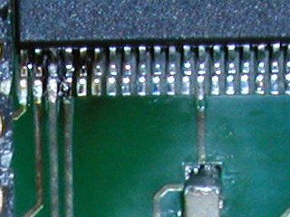
It is still a work-in-progress, but it is detected properly and does produce MIDI playback. The playback is perfect on some instruments, and distorted with others. My current suspicion is a questionable solder joint on one of the flash chips. When I have more time, I will investigate with IWDUMP, to see what the contents of the ICs look like. I know that the chips were successfully programmed and that the contents are identical to the ROM image files, so a solder joint seems likely. Clearer pictures, screenshots and audio samples to follow.
It looks like I was right about the solder joint. The chip on the underside of the board must have had a few pins that weren't as well soldered as they should have been. With that problem rectified, it worked as one would expect, producing clean, distortion-free sound. This is what the UltraSound Properties window had to say about the memory present on the card:
Notice the dual-bank custom ROM. This should put to rest the theories that ROM sizes other than the InterWave power-up default, or AMD standard of 1 MiB, require a custom driver. Under DOS, PLAY.EXE worked fine, as did any MIDI player I tried under Windows 3.1. It should also prove, once and for all, that we can successfully generate our own ROM images.
The next two images show the top and bottom of the ROM daughterboard, respectively:
The bad news is that the board only lasted a few hours before playback became distorted and the ROM stopped being detected altogether. I am still investigating what happened, and I have a few theories that I will look into more carefully when I have time (maybe this evening). So, obviously, there will be no recordings for now. If the answer is that I have to revise the board or order more parts, I will likely hold off until my budget looks a little healthier.
I take that back; the ROM module is not dead, but its behaviour is somewhat peculiar. Usually, if left long enough, it seems it will work another few hours before the symptoms re-appear. I will have to investigate the source of the problem, but should still be able to provide a few recordings a little later.
I am not sure if the behaviour is inherent in the InterWave chip, the particular board I'm using or the ROM module, but it is strange. Every time, after a few hours, it's like the module partially disappears; even a cold boot shows at most one bank, and half of the DRAM often disappears as well. It's as if the bank select signals stop working correctly. Removing the ROM module causes the symptoms to clear, and replacing it makes them come back. Waiting a few hours seems to reliably get everything working again. There must be something I'm missing.
I am beginning to suspect that one of the flash ICs was partially damaged during my initial trials with these chips. I will order a few more when I can, and will test more thoroughly. This also shows why it would be nice to have someone else validate my results on their hardware, and proves that it is essential that I test the upcoming ARGUS ROM modules on real hardware.
If there is a particular MIDI file that you would like me to try, feel free to mention it.
I made a few more modifications to the circuit as a trial, and got it running again. I don't have time to sit around listening to MIDI files for hours today, so I can't test thoroughly yet, but I did have a chance to make a few recordings. The MP3 file contains recordings of two MIDI files; the second one starts around 1:35. I couldn't hear any distortion or excessive noise, but comments are welcome.
EDIT: I am leaving the recording here to show the results at that time, but the playback is not quite correct, due to a bug in the ROMMAKER that has since been corrected (albeit a somewhat sloppy, temporary fix).
I take that back; the ROM module is not dead, but its behaviour is somewhat peculiar. Usually, if left long enough, it seems it will work another few hours before the symptoms re-appear.
I have experienced similar behavior with a PSRAM chip. Noise on the bus was causing the #CS to (very weakly) toggle repeatedly and quickly. This caused the chip to repeatedly perform back to back read/write operations -- out of specification operation. This lead to an internal ground net to gain voltage, slowly over time. Once it reached a certain level, the chip refused all commands and appeared dead. The only way to restore normal operation was to wait (45 minuets or an hour if I recall).
I'm not saying this is the same root cause. That failure was very closely tied to the design on that chip and the memory bus it was on. I'm just trying to show these chips can behave very weirdly.
i updated the parts list with:
- the correct voltage regulator
- oscillators (-> the 16Mhz is low on stock if you take a bit off-valued. better check other sites than digikey for this one if you want the exact values. @shock: is it possible to the take the one from the sheet? [see google sheets link]
a question remais: R17, R18 and some others are marked with "0 Ohm", therefore i assume that NO resistor is used and that R17,R18,... keep empty ? or is it a typo ?
0 ohm resistor is a bridge, you need the pads connected don't leave them unpopulated. You can even use some solder to connect the pads if you can't get 0ohm "resistors" 🤣
a question remais: R17, R18 and some others are marked with "0 Ohm", therefore i assume that NO resistor is used and that R17,R18,... keep empty ? or is it a typo ?
0 ohm resistor is simply a jumper, and YES it should be populated.
Noise on the bus was causing the #CS to (very weakly) toggle repeatedly and quickly. This caused the chip to repeatedly perform back to back read/write operations -- out of specification operation.
I expected something similar to be the cause of the problems I was having, particularly since one of the select signals is just wire-wrapped from one header on the board to a header on the ROM module. While trying to investigate that theory, I made a few revisions to the circuit, and the results seemed to partially support the theory. So, I decided to wire the module so that the second bank was always disabled. Then, figuring that it was also related, I decided to remove one SIMM, to see how much memory was detected.
Those changes led to something quite different: there was more current available, which resulted in a bit of a light show, then this:
Aside from also physically destroying the module, removing that flash IC clarified the explanation: there was still some flux residue under the chip that I hadn't managed to clean, and the flux that I have been using, while very good for soldering, is somewhat conductive (and flammable)! With unrestricted 5V on the select line, right next to a ground pin, and conductive residue still sitting on the edge of the footprint under the chip, you can guess the results (shame on me for not putting a resistor in-line, but it helped provide the explanation in spectacular fashion, which I wouldn't otherwise have had). So, yes, the explanation came with the acrid stench of magic smoke. Fortunately, the GUS seems to have escaped unharmed.
That likely explains the problems I was having with the ROM module all along, and the reasons that removing the module seemed to immediately restore normal operation. Undeterred, I will build another one soon (using different flux!), so that I can test more thoroughly, and am already working on a revised version of the board.
Strange how such an accident can actually turn out constructive for the project. Sure hope the mysterious ROM problems are gone now.
I was wondering about the health of your one GUS card while reading, glad to hear it is unharmed.
Just a quick reminder ... deadline is in 4 days 😉
Currently I have 15 people who signalized interest, yet 8 who paid.
If we get the full 15 people, we can get a gold surface and a different colored soldermask for free (only thing missing compared to the series run would be the lack of hardplated gold connectors).