Cizkaro wrote:I have a Shuttle HOT-409 and naturally the old battery for CMOS has long since leaked and been removed. There is a external ba […]
Show full quote
I have a Shuttle HOT-409 and naturally the old battery for CMOS has long since leaked and been removed. There is a external battery connector with 4 pins on this board I would like to utilize with a battery holder and AA batteries. I have looked around for a pin-out of this header but I am unable to find one. Perhaps someone here knows the pin-out or knows a way perhaps with a multi-meter I could determine which pins are + and - and what actual voltage this mainboard needs to retain CMOS information? I attached some links to the only info I have been able to find.
Links to what info I have found:
http://stephan.win31.de/hot409.htm
http://www.elhvb.com/mboards/shuttle/manuals/hot-409.pdf
Generally these are four pin headers with one pin removed:
+ —
|_||
(If your header doesn’t look like this, simply buzz the GND pins out with the continuity function of your meter. They will be connected to one of the black wires of a 4-pin Molex power connector.)
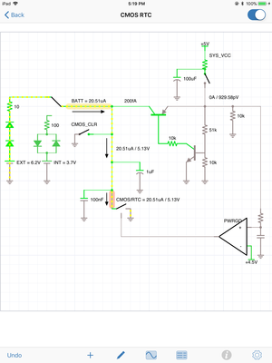
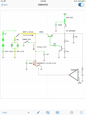
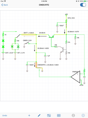
The two GND (=) pins are connected together on the board, you only need to connect one to the battery pack. The + pin usually runs through two series connected diodes, dropping a 6V battery pack down to at least 5.5V (which is the max normal working voltage of most parts). This voltage connects to VCC on the CMOS ram and RTC (discrete or built into part of the chipset). There is also a connection to the same VCC pin from the normal 5V system supply, which goes through an NPN-PNP transistor combination (setup in a darlington configuration), this allows the power supply to override the batteries when the system is on. This setup will also explicitly *not* back feed current to the batteries, so you can use primary cells.
You can verify the series connected diodes by placing your multimeter into the diode test function and connecting between the External Battery + pin on the motherboard and the non-GND pin of the CMOS clear jumper. You should also do a voltage reading between Ext. Batt + and GND with the system turned on; verify you don’t get more than a few millivolts (this is to make sure current isn’t being fed to the batteries).
There should also be a 3W jumper that allows you to switch between an external or onboard battery. (This switches between two series connected diodes for a 6V pack and two back to back diodes for a 3.7V NiCd onboard battery (which allows charging).
On my 386 system I use a 4xAAA pack. Works great!
Also, if your system doesn’t have a pin header for an external pack you can always solder male pins to the battery footprint on the motherboard. In that case make sure you put a single 1N4148 diode in-line with the positive battery lead, to drop the voltage and prevent the pack from charging:
BATT 6V Pos +———+—[ >|—+——+ Motherboard
Any sufficiently advanced technology is indistinguishable from magic. (E.g., Cheez Whiz, RF, Hot Dogs)