I am able to open the electronic schematic editor (Eeschema), with a warning saying the file was created on a newer version.
When I try to open the printed circuit board editor (pcbnew), I get an error: Error loading board. KiCad was unable to open this file, as it was created with a more recent version than the one you are running. To open it, you'oll need to upgrade KiCad. Oh well.
Looking at the PCB calculator, it seems like a lot (all?) parameters are calculated for you based on user inputs, like current, temp rise, trace length, and resistivity. It then tells you what trace width, thickness and spacing to use. So looking at some of these inputs, I would probably pick a maximum freq. of 100 MHz.
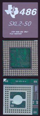
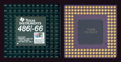
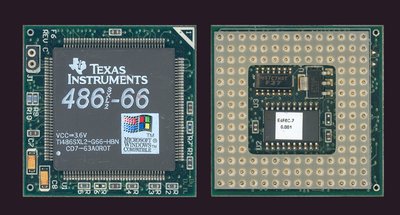
As for the max current draw, some estimate will be needed. From the SXL2 data book, we see that a 3.3 V CPU at 40 MHz will have a max draw of 400 mA. At 50 MHz, 500 mA. We don't have any data for 66, 80, or 100 MHz, nor for 3.6 V - 4.0 V operation. I'm guessing 3.3 V at 100 MHz would be 1000 mA. At 3.6 V, perhaps 1100 mA? At 4 V, perhaps 1400 mA? This uncertainty is why I had sourced a 3 A max regulator rather than a 1.5 A. There is a 1.5 A version (2915x) which is probably fine though. I tested the 3A version it under loads of 730 mA and 360 mA and the output voltage didn't change at all.
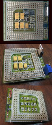
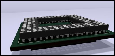
For mounting the VRM, I was wondering if it would be possible to surface mount it inside the PGA168 socket? Not as ideal for heat dissipation, but I see it done all the time with 486 interposers running Am5x86 and Cx5x86 chips. If the VRM can be surface mounted inside the PGA168 socket, there are TO-252 and TO-263 variants available. I believe TO-252 is slightly smaller than TO-263. I think the top tab is also GND, so have some GND pad available to solder it to. It would also be nice to do away with the trimmer for a cleaner look. I originally thought about using a jumper block for voltages, 3.3 V, 3.45 V, 3.6 V, 3.7 V, 3.8 V, and 3.9 V. This would require 6 different resistors and a jumper block, so it doesn't really save space over the trimmer. However, you would be able to conceal the jumper block under the CPU. Rather than a jumper bock, there are low profile dip switches I've seen fit under the CPU on the Trinity Works Powerstacker; it contains 6 switch positions. So on the surface, we'd just have a 3-pin jumper, one pin for MEMW# and the other two for 5V and GND (fan).
By the way, on my prototype, I am using a 121-ohm resistor for R2, a Bourns PV36 500-ohm trimmer (currently set around 230-ohms). Vref=1.24 V.
I'll try to install KiCAD 5.0, however, I doubt it will work on XP. EDIT: When I look at the Kicad homepage, it says that version 4.0.7 is current stable release for Windows 32-bit and 64-bit and Ubuntu.
Plan your life wisely, you'll be dead before you know it.