Reply 20 of 67, by reenigne

Rank
Oldbie
- Rank
- Oldbie
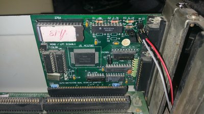
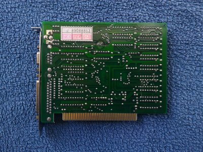
wrote:wrote:that card looks like the myriad cga/mda/hercules cheap clone cards , no way color means EGA ... not a bad card especially for mda/herc
Man.. I thought I had an excuse to buy a scope 😀
Well... you could still make your own CGA card from scratch, just for fun, even if you don't actually need to! You'd surely need a scope to debug it... (Though I'd have said that about cloning an Adlib card as well - impressive that you did that with no scope!)