It's time to optimize again! 🤣 With that many ICs on the maximum size board it is always important.
Remember when OPL2 block was shrinked from 59 mm to 49 mm?
There is one thing I suggest you add, which is at least 12bit address decode. With 10 bits you get lot of mirrors which can make coexisting with other devices difficult, i.e something on your card at $210 will also appear at $610, $A10 and $E10. For example on my card some default addresses are $A20 and $A28 and with something that uses 10 bit decode there will be a clash at $220 and $228. Things like AWE32 cards and some others also put things at addresses beyond $3FF.
You could gate AEN if A10, A11 are not zero, it will only need one extra chip and won't require you to redesign any of the subcomponents. If the chip used allows more lines to be looked at, that would be good too. On my card there's 12 bit decode on chipset level and 16bit is achieved via CPLD looking if A12...A15 are zero and only passing AEN then.
EDIT: corrected a fault.
Last edited by Tiido on 2018-08-17, 00:52. Edited 1 time in total.
There is one thing I suggest you add, which is at least 12bit address decode. With 10 bits you get lot of mirrors which can make coexisting with other devices difficult, i.e something on your card at $210 will also appear at $610, $A10 and $E10. For example on my card some default addresses are $A20 and $A28 and with something that uses 10 bit decode there will be a clash at $220 and $228. Things like AWE32 cards and some others also put things at addresses beyond $3FF.
You could gate AEN if A10, A11 are not zero, it will only need one extra chip and won't require you to redesign any of the subcomponents. If the chip used allows more lines to be looked at, that would be good too. On my card there's 12 bit decode on chipset level and 16bit is achieved via CPLD looking if A16...A19 are zero and only passing AEN then.
I've thought about that some time ago, but not long enough. That's a valid point.
On one side, all those boards that I cram in the FMonster were using 10-bit address just fine. But on the other side, if this board will be put in more "modern" machine with ISA 16-bit slots and more hardware...
Will 12 bit be enough? Even on the ISA 8-bit slot we have 20 bits of address (A0 to A19). What is reasonable limit for "address depth" to dive into?
I made a mistake in my last post, it is A12...A15 and not A16...A19, IO accesses can only span 0000...FFFF. I have not actually seen any ISA device that goes beyond 12bits but Multimedia PC specification calls for 16bit address decode and lot of sound chip datasheets I have looked at make it out to be a big deal too (but probably only to conform to MPC spec).
I have read that Pentium and newer boards where ISA is behind a bridge forward all 0000...0FFF to ISA but beyond only if a PCI device doesn't claim the access to itself. Probably applies to 486 with PCI slots too. I no longer remember the source but it probably was some chipset datasheet. So from that, 12 bits should definitely be done, then mirrors only happen in the "PCI area". More could be a bonus, if you can go for it, I could so I did.
Thank you very much!
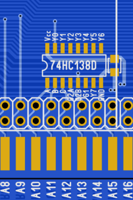
I think that throwing another 74HC138 will solve the problem. It can take up to five "0" inputs and give a "0" at the output.
For example, A -> A10, B -> A11, C -> A12, G2A -> A13, G2B -> AEN, G1 -> +5V. Take the "new" AEN from Y0 output and there you have 14-bit decoder. 😎
I have not actually seen any ISA device that goes beyond 12bits
The IBM Music Feature Card does, its base address is at 2A20h.
And this clashes with Game Blaster/Sound Blaster cards at 220h, because those only do 10-bit address decoding, so they mirror themselves in the IMFC address range.
For decoding 12-bit address for space saving you can use only 2 ICs - one 74x138 and one 74x4075 (triple 3-input OR):
Route all constant 0s to 2 of 4075's ORs (A1, A2, A4, A6, A10, A11), output them to 3rd OR and also connect AEN here. Route variable A5, A7 and A8 to 138's A0-A2 inputs, constant 1 A9 to OE of 138, constant 1 A3 via free NOT on 74x04 to /OE1 and output from 3rd OR to /OE2. And corresponding outputs from 138 to jumpers.
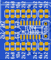
Also you can use more relaxed filter on output - drop some caps and resistors. And use rail-to-rail opamp like LMC6484 instead of TL074 and get rid of two 9V regulators and still have enough headroom.
For decoding 12-bit address for space saving you can use only 2 ICs - one 74x138 and one 74x4075 (triple 3-input OR):
Route all constant 0s to 2 of 4075's ORs (A1, A2, A4, A6, A10, A11), output them to 3rd OR and also connect AEN here. Route variable A5, A7 and A8 to 138's A0-A2 inputs, constant 1 A9 to OE of 138, constant 1 A3 via free NOT on 74x04 to /OE1 and output from 3rd OR to /OE2. And corresponding outputs from 138 to jumpers.
I don't get why I should use two ICs (and introduce new one into the BOM - 4075) for 12-bit decoding, when I already have 14-bit decoding with just one 74HC138? It is one IC for the whole board and all blocks have their own address decoders, different from each other. 😕
Also you can use more relaxed filter on output - drop some caps and resistors. And use rail-to-rail opamp like LMC6484 instead of TL074 and get rid of two 9V regulators and still have enough headroom.
The reason why I use 78L09 + 79L09 is because of noise on the power rails. I want it to be as low as possible for analog parts of the circuit. That's why I use linear regulators and not one pair for the whole board, but local regulators for each block. It seems like it should pass power requirements for +/-12 V rails of ISA bus.
As for filtering, there will be one common 3rd order low-pass filter at the output after the mixer.
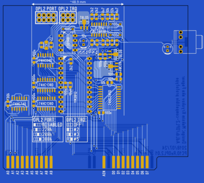
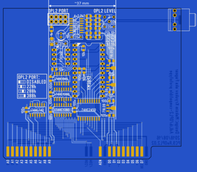
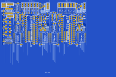
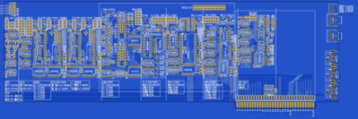
And here are new updates on optimization. ISSI block was taking too much space. So, month later...
Clock generator + two ISSI blocks were 109 mm. Now Clock generator + ISSI address decoder (which was missing on the example earlier) + two ISSI blocks are 97 mm! And if I exclude address decoder (as on older image) total length will be 83 mm.
All those optimizations gave me about 49 mm free length at the right side for something else. Or just for shrinking the whole board and get cost reduced.
I don't get why I should use two ICs (and introduce new one into the BOM - 4075) for 12-bit decoding, when I already have 14-bit decoding with just one 74HC138? It is one IC for the whole board and all blocks have their own address decoders, different from each other. 😕
When I guess I misunderstood your above discussion on 12-bit decoding with Tiido which you ended up with:
Fagear wrote:
Thank you very much!
I think that throwing another 74HC138 will solve the problem.
😀
Fagear wrote:
The reason why I use 78L09 + 79L09 is because of noise on the power rails. I want it to be as low as possible for analog parts of the circuit. That's why I use linear regulators and not one pair for the whole board, but local regulators for each block. It seems like it should pass power requirements for +/-12 V rails of ISA bus.
The idea was that you can feed rail-to-rail with only a single +5V supply from your 7805 regulator having enough headroom.
There are a lot of sound sources and creating good VREF for all of them takes bunch of extra parts and will yield worse noise perfromance than having stuff biased to ground and sit between positive and negative rails.
Tandy PSG, CMS, SSI, 8-bit DAC do not have ANY filtering at the output at all! And all those can produce very high harmonics (with square waveforms).
Problems will start as soon as the signal goes to less-than-perfect ADC. Probably ok if goes to dumb amp with analog timbre block that does the job of filtering higher frequencies.
Also, I'm a bit concerned about the use of TL074 etc. This is decent all-around amp but not considered HiFi. Good old 5532 are still recommended for audio, if you are on a budget. But they have no quad version 🙁
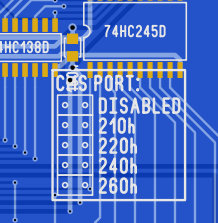
If you think that I have to allow more addresses on jumpers from "hidden" list above - feel free to let me know.
I suggest adding 0x3BC to that list.
That is where early PCs had their printer port (original MDA card and many MDA/Hercules clones).
0x3BC, 0x378 and 0x278 are the official addresses for LPT1, LPT2 and LPT3.
However, 0x378 probably became the 'default' because that's what the extra printer port card from IBM used, and if you didn't have an MDA+printer card in your machine, the 0x278 address would become the first printer port.
Problems will start as soon as the signal goes to less-than-perfect ADC. Probably ok if goes to dumb amp with analog timbre block that does the job of filtering higher frequencies.
That's why I'm concerned and why I'm putting 3rd order lowpass right after final mixer.
noop wrote:
Also, I'm a bit concerned about the use of TL074 etc. This is decent all-around amp but not considered HiFi. Good old 5532 are still recommended for audio, if you are on a budget. But they have no quad version 🙁
Dual-opamp-only is the reason. I'm very restricted with board space in this project and four opamps in one IC is a must. We'll see how it will go. Prototype boards are already in Moscow, I'll be able to assemble and check debug-boards soon. Including mixer board.
Scali wrote:I suggest adding 0x3BC to that list.
That is where early PCs had their printer port (original MDA card and many MDA/Hercules clo […] Show full quote
I suggest adding 0x3BC to that list.
That is where early PCs had their printer port (original MDA card and many MDA/Hercules clones).
0x3BC, 0x378 and 0x278 are the official addresses for LPT1, LPT2 and LPT3.
However, 0x378 probably became the 'default' because that's what the extra printer port card from IBM used, and if you didn't have an MDA+printer card in your machine, the 0x278 address would become the first printer port.
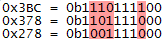
I thought about it. But there are too many different bits between those three addresses, two 74HC138s can not do that. It will require at least three of those. And it is board space again.
Also, yes, 0x3BC officially is "the first" LPT port in the IBM PC, but if it is not present, 0x378 becomes LPT1. And 0x378 is the default port on most systems, I think. I need to investigate software options fot that matter. What different "Covox-enabled" games and trackers can address. 😕
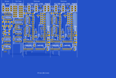
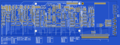
While I'm waiting for debug boards I finished in-board-bus rerouting and made connections for each block. Now I have to figure out what analog part of the board will look like, after that I'll get the idea for how far I can move all blocks to the mounting bracket.
1address dec/hex, len, description
200h 	0     2 bytes 	Base I/O address for serial port 1 (communications port 1 - COM 1)
302h 	2     2 bytes 	Base I/O address for serial port 2 (communications port 2 - COM 2)
404h 	4     2 bytes 	Base I/O address for serial port 3 (communications port 3 - COM 3)
506h 	6     2 bytes 	Base I/O address for serial port 4 (communications port 4 - COM 4)
608h 	8     2 bytes 	Base I/O address for parallel port 1 (printer port 1 - LPT 1)
70Ah 	10    2 bytes 	Base I/O address for parallel port 2 (printer port 2 - LPT 2)
80Ch 	12    2 bytes 	Base I/O address for parallel port 3 (printer port 3 - LPT 3)
90Eh 	14    2 bytes 	Base I/O address for parallel port 4 (printer port 4 - LPT 4) (Only found in PC/XT systems)
so, word at 0x40:08 - LPT1 IO address, just like 0x40:0 has 0x3F8, 0x40:2 has 0x2F8
now, does not mean apps obey. many things hardcode 3F8/2F8, so swapping that in the BDA often has no affect. Chaning what is LPT1 IO might not always have impact.