VOGONS


Reply 460 of 844, by bjwil1991

User metadata
Rank l33t
Rank
l33t

Ah, RAMBUS. The one thing I don't like is the RAMBUS memory is like SCSI drives: requires termination or dummy memory in 2 slots in order for it to boot, otherwise, it won't POST or beeps in a loop. I have an Intel D850GB motherboard that uses RAMBUS memory, and it's pretty cool to see that. Another thing that's mind blowing is the Nintendo 64 uses RAMBUS memory as well. Good looking board as well.

Discord: https://discord.gg/U5dJw7x
Systems from the Compaq Portable 1 to Ryzen 9 5950X
Twitch: https://twitch.tv/retropcuser

Reply 463 of 844, by amadeus777999

User metadata
Rank Oldbie
Rank
Oldbie
bjwil1991 wrote:

Ah, RAMBUS. The one thing I don't like is the RAMBUS memory is like SCSI drives: requires termination or dummy memory in 2 slots in order for it to boot, otherwise, it won't POST or beeps in a loop. I have an Intel D850GB motherboard that uses RAMBUS memory, and it's pretty cool to see that. Another thing that's mind blowing is the Nintendo 64 uses RAMBUS memory as well. Good looking board as well.

I only have one board, a P4 one, with Rambus and in a memory benchmark it gives approximately 2 times the performance of SDRam. I think it is around 1GB- vs 2 GB/s.

Reply 464 of 844, by Robert B

User metadata
Rank Oldbie
Rank
Oldbie

Lazerhawk - Dream Machine

Gigabyte GA-8TM REV:1.0 aka THE FLOP[/size]

I bought this motherboard before I got the ECS P4ITA at a time when I really wanted to have a RAMBUS S423 setup.

I found the Gigabyte GA-8TM on a local add site and I paid under 3 EUR for it. It was listed as not working and I thought that for such a low sum of money what could possibly go wrong? Little did I know that this was going to be a money pit...it all starts with an introduction fee and then better fasten your seatbelts!

ALL ABOARD!

I contacted the seller and soon I held in my hands the object of my desire.

Initial impressions were good. The motherboard had some signs of damage but all in all it looked ok.

GA-8-TM-001.jpg

I mounted an intel P4 1.7GHz SL57W CPU, I straightened some bent pins on the WINBOND W83627HF-AW chip, then I powered up the motherboard.

GA-8-TM-002.jpg GA-8-TM-003.jpg GA-8-TM-004.jpg

NOTHING! No POST. No beeps. DEAD. The only time when the motherboard showed signs of life was when there were no RAM sticks installed and the PC SPEAKER gave the NO RAM ERROR BEEP CODE.

I conducted a close inspection and I found more problems. Broken plastic bits from the parallel port. Bent fins on the northbridge heatsink. CPU socket with signs of damage. USB port with bent pins.

GA-8-TM-005.jpg GA-8-TM-006.jpg GA-8-TM-007.jpg GA-8-TM-008.jpg GA-8-TM-009.jpg GA-8-TM-010.jpg

Surprisingly there were NO SMD componets missing from the PCB. This made me to take the decision to do whatever it was in my power to save this motherboard. (Bad choice here)

I decided to remove the BIOS chip and install a PLCC32 socket for easy BIOS update. I also bought new USB ports for the motherboard.

GA-8-TM-011.jpg

Removing the BIOS chip and installing the PLCC32 socket was a breeze.

GA-8-TM-012.jpg GA-8-TM-013.jpg GA-8-TM-014.jpg GA-8-TM-015.jpg GA-8-TM-028.jpg

The removal of the USB ports was another matter. I dont have a hot air station so I had to use brute force in a gentle way and I removed the damaged ports bit by bit. At that moment it became clear that my puny 40W soldering iron wasnt enough so I had to use something stronger. The multilayer PCBs suck up the heat faster as they have a bigger surface and when a smaller soldering iron is used, the solder doesnt remain fluid for the required amount of time and also the solder joints arent good.

I brought the THE BIG GUNS in the shape of an old 100W soldering gun with a modified tip. I simply didnt have anything else available. 😁

I have to mention that up until that moment I didnt do anything close to the scale of the operation I was to undertake and my experience was limited.

Using the 100W beast I got decent results and in the end I became an expert in using this unyielding weapon. (Once a barbarian always a barbarian). Later on, I used this soldering gun on many occasions with zero problems. No burn marks on the PCB, zero damaged traces, zero capacitor casualties . Replacing a capacitor is a piece of cake with this tool.

I do not recommed that you do the same, though. Your mileage might vary.

GA-8-TM-016.jpg GA-8-TM-017.jpg GA-8-TM-018.jpg GA-8-TM-019.jpg GA-8-TM-020.jpg GA-8-TM-021.jpg GA-8-TM-022.jpg GA-8-TM-023.jpg

After a lot of work I was ready for another test. I updated the BIOS chip using a MiniPRO TL866A programmer and I powered up the motherboard. The result was A BIG FAT ZERO!

STILL NO CHANGE!

Days have passed but my mind was still searching for a solution.

I conducted another inspection of the motherboard.

This time I saw that a capacitor near the memory slots was MIA.

GA-8-TM-024.jpg

I searched on the internet for pictures that would reveal the specs of the missing capacitor but I found nothing. Fuzzy pictures with a low resolution. I wanted to at least find the colour of the missing capacitor. Wasted hours...

In the end I found this picture from Computex Taipei 2001.

GA-8-TM-025.jpg

https://www.ixbt.com/news/hard/index.shtml?02/07/11

I stared at the picture for many minutes. The missing capacitor was dark green. There were many dark green capacitors on the board but they had different sizes so I was back to square one.

In the end I came up with the following solution: SHADDOW ANALYSIS.

I took pictures with my motherboard im such a way that it would emulate the Computex Taipei 2001 picture. This way I was able to find the approximate size of the missing capacitor. As now I had information about the colour and the size of the missing capacitor I could determine the specs using a neighbouring capacitor.

The specs of the missing capacitor were 1200uf 6.3V. I couldnt find one locally so I used a 1500uf 6.3V capacitor.

GA-8-TM-026.jpg GA-8-TM-027.jpg GA-8-TM-029.jpg

I tested again the motherboard. STILL NO CHANGE!!!

I tossed the board in a box ready to give up.

Weeks have passed. Thinking that maybe my 1.7GHz P4 was dead, I bought another Pentium 4 1.5GHz SL4SH CPU and I tried again.

GA-8-TM-030.jpg

STILL NO CHANGE! NO POST. NO BEEP. NOTHING!

I bought a new memory kit: 1GB RIMM 4x256MB PC600.

STILL NO CHANGE!

While I passed my hand over the motherboard I felt that a few GSC capacitors, were hotter than the rest, so I replaced 8 GSC 330uf 25V capacitors with SAMWHA 330uf 50V.

GA-8-TM-031.jpg GA-8-TM-032.jpg GA-8-TM-033.jpg

NEW TEST. STILL NO CHANGE!

I replaced the 1200uf 6.3V capacitor with a 1500uf 6.3V. I replaced other capacitors...I removed the northbridge heatsink and I replaced the thermal paste.

STILL NO CHANGE!

I bought a cheap PCI diagnostic card- PCI SMART DEBUGGER CARD but I found nothing new. Money down the drain...I wouldn't buy this debugger card again and I would buy something better instead.

The PCI debugger card at least revealed that the +3.3V +5V +/-12V voltages were OK.

The motherboard was stuck at: "control to INT 19H boot loader".

GA-8-TM-035.jpg

I searched for a solution for hours and nothing worked.

I connected a HDD, a DVD-ROM and a floppy unit thinking that maybe this was the problem. I tried multiple BIOS versions. I checked the jumpers. All was for nothing.

When I connected the HDD on the second IDE port the PCI debugger card showeed nothing.

Problems, problems and even more problems.

Over the course of the last test sessions I saw that the southbridge chip got extremely hot. I couldnt keep my finger on it for more than two seconds. For sure this was the culprit for all of my problems. This also meant that the motherboard was toast.

In a gesture of maximum frustration I dumped the board in the box and I tried to forget it.

Even so I wasnt ready to call it quits and I bought some cheap Chong CD110X capacitors and I replaced the VRM caps. 7 pcs in total. I would change them with japanese caps if the motherboard would spring into life.

GA-8-TM-036.jpg GA-8-TM-037.jpg GA-8-TM-038.jpg

The motherboard showed just a flatline.

YEP you have guessed it! 😁 NO CHANGE!!!

If I add up the time, effort and money we arrive at a respectable sum of money. Maybe I should've paid the full price and get a working board from EBAY LIKE A BO$$.

This board was a total faillure!

From this endeavour I also got some positive aspects. Now I can change capacitors with zero headaches. Dead meat was useful after all. 😁

Over and out! Nothing more to add. I dont want to hear about Gigabyte GA-8TM a long time from now.

Sometimes it's better to quit while you are ahead instead of giving everything for nothing...live and learn. This mishap made me reluctant to buy motherboards that I would've bought in the past. Now I even look to see what brand of capacitors are on the board before I make the purchase.

gallery: https://postimg.cc/gallery/1ey3rxtgk/

This was THE FLOP!

GA-8-TM-039.jpg

More later.

Reply 465 of 844, by Robert B

User metadata
Rank Oldbie
Rank
Oldbie

Toto - Hold The Line

NEXT WEEK: THE BIG Flea Market Surprise Episode!

1. Adaptec 1200A RAID Controller
2. KINGMAX DDR400 / KINGMAX HARD-CORE DDR500
3. NVIDIA Quadro FX 1000 / ZALMANN VF700 AlCu
4. Butterfly Intel i740 8MB AGP
5. RIMM
6. 370CPU REV 1.0 slotket / Intel Celeron 900MHz/100 SL5LX
7. ASUS AGP-V6800DDR/32M(TVR) - Geforce 256 DDR / Asus V6800 DELUXE
8. Thermaltake Super Orb / Athlon XP 1900+ *** AX1900DMT3C *** AGOIA0152RPBW / Athlon XP 2800+ *** AXDA2800DKV4D *** ADYHA0512RPMW
9. Creative Sound Blaster 16 *** Creative Labs CT2890 *** Vibra16SPNP
10. Gigabyte GA-622-16 REV 1.0 *** Riva TNT 2 M64 16MB AGP
11. GUS ACE 1.1 *** ADVANCED GRAVIS ULTRASOUND ACE VERSION 1.1

147 pictures! 😁

More later.

Reply 466 of 844, by PcBytes

User metadata
Rank Oldbie
Rank
Oldbie

I just happened to come across an gem that was dead just as in your case (although my board was a GA-8IK1100, i875P) so I kinda feel your pain after trying to replace the burnt SB myself (mine was a FW82801ER, bigger than yours so it was a bit easier to handle I guess) and ending up ripping traces. Someday I might actually hunt down a GA-8IK1100 just for the sake of it and pair it up with a Winfast A380 Ultra. (I have the latter, just it's artefacting, might see how to come up with a plan to reflow it 😀 )

"Enter at your own peril, past the bolted door..."
Main PC: i5 3470, GB B75M-D3H, 16GB RAM, 2x1TB
98SE : P3 650, Soyo SY-6BA+IV, 384MB RAM, 80GB

Reply 467 of 844, by Robert B

User metadata
Rank Oldbie
Rank
Oldbie

Eminem - Bitch Please II (Feat. Dr. Dre & Xzibit & Snoop Dogg)

FLEA MARKET SURPRISE! - (the big version)

As you probably know by now, the Flea Market Surprise episodes present components that I found at the local flea market. They have been bought at very low prices. 2-5 EUROS max.

F.M.S. because you never know what you might find there!

The presentation is short and I let the pictures tell the story.

Let's meet the FRESH MEAT! Fresh from the gutter I mean. 😁 By the time I'm done with them, they will shine brighter than a diamond in the g0at$ a$$!!! 😁

1. Adaptec 1200A RAID Controller
2. KINGMAX DDR400 / KINGMAX HARD-CORE DDR500
3. NVIDIA Quadro FX 1000 / ZALMANN VF700 AlCu
4. Butterfly Intel i740 8MB AGP
5. RIMM
6. 370CPU REV 1.0 slotket / Intel Celeron 900MHz/100 SL5LX
7. ASUS AGP-V6800DDR/32M(TVR) - Geforce 256 DDR / Asus V6800 DELUXE
8. Thermaltake Super Orb / Athlon XP 1900+ *** AX1900DMT3C *** AGOIA0152RPBW / Athlon XP 2800+ *** AXDA2800DKV4D *** ADYHA0512RPMW
9. Creative Sound Blaster 16 *** Creative Labs CT2890 *** Vibra16SPNP
10. Gigabyte GA-622-16 REV 1.0 *** Riva TNT 2 M64 16MB AGP
11. GUS ACE 1.1 *** ADVANCED GRAVIS ULTRASOUND ACE VERSION 1.1

1. Adaptec 1200A RAID Controller

Nothing fancy.

Adaptec-1200-A-01.jpg Adaptec-1200-A-02.jpg Adaptec-1200-A-03.jpg

gallery: https://postimg.cc/gallery/2e5uj4gpw/

2. KINGMAX DDR400 / KINGMAX HARD-CORE DDR500

Ahhh GooD Ol' KINGMAX!

Cleaned, tested and put in the stash o' RAM.

DDR400-500-01.jpg DDR400-500-02.jpg DDR400-500-03.jpg DDR400-500-04.jpg DDR400-500-05.jpg DDR400-500-06.jpg DDR400-500-07.jpg DDR400-500-08.jpg DDR400-500-09.jpg DDR400-500-10.jpg DDR400-500-11.jpg

gallery: https://postimg.cc/gallery/36vxyekro/

3. NVIDIA Quadro FX 1000 / ZALMANN VF700 AlCu

Nice card but DEAD. The Zalmann VF700 cooler has most likely damaged the card. Even the heatspreader from the graphic chip had its corners reaching for the sky.

It is possbile that maybe the card was put under a twisting action but I didnt find any evidence on the PCB to sustain this. Most likely, the retaining system of the Zalmann cooler is the culprit here. The two anchoring points put a lot of strain on the PCB and the diagonal backplate is not doing her job well.

I used to like this type of coolers but I wouldnt leave one mounted on any card for more than a few hours.

FX1000-01.jpg FX1000-02.jpg FX1000-03.jpg FX1000-04.jpg FX1000-05.jpg FX1000-06.jpg FX1000-07.jpg FX1000-08.jpg FX1000-09.jpg FX1000-10.jpg FX1000-11.jpg FX1000-12.jpg FX1000-13.jpg FX1000-14.jpg

gallery: https://postimg.cc/gallery/1kyanmh0k/

4. Butterfly Intel i740 8MB AGP

i740!

Butterfly-i740-01.jpg Butterfly-i740-02.jpg Butterfly-i740-03.jpg Butterfly-i740-04.jpg Butterfly-i740-05.jpg Butterfly-i740-06.jpg Butterfly-i740-07.jpg

gallery: https://postimg.cc/gallery/vgfe0eck/

5. RIMM

Squeaky clean.

RIMM-01.jpg RIMM-02.jpg

gallery: https://postimg.cc/gallery/1srwjzw6c/

6. 370CPU REV 1.0 slotket / Intel Celeron 900MHz/100 SL5LX

You never know when you might need a slotket! Better buy them when you see them!

Slotket-01.jpg Slotket-02.jpg Slotket-03.jpg Slotket-04.jpg Slotket-05.jpg

gallery: https://postimg.cc/gallery/g1ha00x0/

7. ASUS AGP-V6800DDR/32M(TVR) - Geforce 256 DDR / Asus V6800 DELUXE

2.2 EUROS for a GF256 DDR? HELL YEAH!

Unfortunately the card has issues. A CHRONTEL CH7005C-T chip has signs of damage. The card shows artifacts.

So much for my cheap GF256 DDR...

I repaired the cooling system and I cleaned the card well. No dirty parts in my collection!

GF256-DDR-01.jpg GF256-DDR-02.jpg GF256-DDR-03.jpg GF256-DDR-04.jpg GF256-DDR-05.jpg GF256-DDR-06.jpg GF256-DDR-07.jpg GF256-DDR-08.jpg GF256-DDR-09.jpg GF256-DDR-10.jpg GF256-DDR-11.jpg GF256-DDR-12.jpg GF256-DDR-13.jpg GF256-DDR-14.jpg GF256-DDR-15.jpg GF256-DDR-16.jpg GF256-DDR-17.jpg GF256-DDR-18.jpg GF256-DDR-19.jpg GF256-DDR-20.jpg GF256-DDR-21.jpg GF256-DDR-22.jpg GF256-DDR-23.jpg GF256-DDR-24.jpg GF256-DDR-25.jpg GF256-DDR-26.jpg GF256-DDR-27.jpg

gallery: https://postimg.cc/gallery/3adtexhus/

8. Thermaltake Super Orb / Athlon XP 1900+ *** AX1900DMT3C *** AGOIA0152RPBW / Athlon XP 2800+ *** AXDA2800DKV4D *** ADYHA0512RPMW

I'll tell you what is the specialty of the TT Super ORB...to make a lot of racket! Man this cooler is noisy as hell! 😁

CPU-TT-01.jpg CPU-TT-02.jpg CPU-TT-03.jpg CPU-TT-04.jpg CPU-TT-05.jpg CPU-TT-06.jpg CPU-TT-07.jpg CPU-TT-08.jpg CPU-TT-09.jpg CPU-TT-10.jpg

gallery: https://postimg.cc/gallery/2vvj60vj8/

9. Creative Sound Blaster 16 *** Creative Labs CT2890 *** Vibra16SPNP

Mint!

CT2890-01.jpg CT2890-02.jpg CT2890-03.jpg CT2890-04.jpg CT2890-05.jpg CT2890-06.jpg CT2890-07.jpg CT2890-08.jpg CT2890-09.jpg CT2890-10.jpg CT2890-11.jpg CT2890-12.jpg CT2890-13.jpg CT2890-14.jpg CT2890-15.jpg CT2890-16.jpg CT2890-17.jpg CT2890-18.jpg

gallery: https://postimg.cc/gallery/2nbqlbmw4/

10. Gigabyte GA-622-16 REV 1.0 *** Riva TNT 2 M64 16MB AGP

A TNT2 M64 with a TURBO JUMPER? Who would've thought? 😁

GA-622-01.jpg GA-622-02.jpg GA-622-03.jpg GA-622-04.jpg GA-622-05.jpg GA-622-06.jpg GA-622-07.jpg GA-622-08.jpg GA-622-09.jpg GA-622-10.jpg GA-622-11.jpg GA-622-12.jpg GA-622-13.jpg GA-622-14.jpg GA-622-15.jpg GA-622-16.jpg GA-622-17.jpg GA-622-18.jpg GA-622-19.jpg GA-622-20.jpg GA-622-21.jpg GA-622-22.jpg

The 3dmark99 scores are similar as the benchmark ran at a resolution of 800x600(CPU limited). If I would've used a 1024x768 resolution the performance increase coming from 125/150 to 160/160 would've been more visible.

gallery: https://postimg.cc/gallery/2z2dpki3o/

11. GUS ACE 1.1 *** ADVANCED GRAVIS ULTRASOUND ACE VERSION 1.1

IMMACULATE! and RED!

GUS-ACE-01.jpg GUS-ACE-02.jpg GUS-ACE-03.jpg GUS-ACE-04.jpg GUS-ACE-05.jpg GUS-ACE-06.jpg GUS-ACE-07.jpg GUS-ACE-08.jpg GUS-ACE-09.jpg GUS-ACE-10.jpg GUS-ACE-11.jpg GUS-ACE-12.jpg GUS-ACE-13.jpg GUS-ACE-14.jpg GUS-ACE-15.jpg GUS-ACE-16.jpg GUS-ACE-17.jpg GUS-ACE-18.jpg GUS-ACE-19.jpg GUS-ACE-20.jpg GUS-ACE-21.jpg GUS-ACE-22.jpg GUS-ACE-23.jpg GUS-ACE-24.jpg GUS-ACE-25.jpg GUS-ACE-26.jpg GUS-ACE-27.jpg GUS-ACE-28.jpg

gallery: https://postimg.cc/gallery/fpkxt50k/

This was THE BIG F.M.S.!

Enjoy!

IceCube - Check Yo Self

More later.

Reply 468 of 844, by bjwil1991

User metadata
Rank l33t
Rank
l33t

Huh? Where'd you find the GUS ACE card? I can never find one on eBay.

Discord: https://discord.gg/U5dJw7x
Systems from the Compaq Portable 1 to Ryzen 9 5950X
Twitch: https://twitch.tv/retropcuser

Reply 471 of 844, by Robert B

User metadata
Rank Oldbie
Rank
Oldbie

@SirNickity - No need for envy as I'm sure that you'll find yours soon. Life works in mysterious ways. 😀

Haddaway - Rock My Heart

AUREAL - great sound cards that I never owned...until today

In regard to the sound cards that I have owned over the years I have nothing to brag about.

My progression was as it follows:

  • ESS1868 ISA - AMD 5x86,
  • Creative 128 PCI - onboard MS-6154 Celeron 366A,
  • SiS7012 AC'97 audio controller - ECS K7S5A Duron 1200MHz,
  • Creative Sound Blaster Live! 5.1 Digital,
  • RealTek ALC201A AC'97 CODEC - ECS K7VTA3 Athlon XP 1900+,
  • NVIDIA SoundStorm™ - Abit NF7-S V2.0 Athlon XP 2800+,
  • Realtek ALC889A codec - Gigabyte EP35-DS3R E8400,
  • Creative Audigy SE 7.1/PCI Bulk
  • Realtek® ALC889 8-Channel High Definition Audio CODEC - ASUS Maximus IV Extreme-Z 2600K,
  • Creative Sound Blaster ZX.

One fact is obvious. In most instances I never had high-end sound cards and I never had or used AUREAL sound cards.

Back in the day, sound cards were pretty expensive and I couldn't justify the price that could amount to a sum of money equivalent with a new motherboard, more RAM or even a video card upgrade.

So, I used whatever I could afford and I didnt feel that I was missing out on something.

The first sound card that opened my eyes was a Creative Sound Blaster Live! 5.1 Digital. Even now I can relive the moment I installed the DEMO CD and I was blown away. Lightning sounded realistic, helicopters almost flew above you, shots were taking place near you, what could I say, the whole package was another experience.

After my first 2.0 speaker setup, something bland, low end, made from cheap plastic and of small size, branded ISO TECH Multimedia, I bought a 4.1 Jazz Speakers setup. Together with the Creative SB LIVE! 5.1 Digital they were all I wanted. All of this was taking place when 5.1 was the new buzz word. I wanted a 5.1 speaker setup but I couldn't afford one. They came later in the shape of a Jazz Speakers 5.1 J9911 2000W PMPO! 😁 Goold Ol' PMPO...instead of RMS. Live an learn. The new 5.1 speaker setup didnt rise up to my expectations. I had problems with the 5.1 implementation in games and movies. Besides some sounds I heard in shooters and car simulators I didnt feel a thing. The fact that the speakers were entry level didnt help either. In 90% of situations the rear speakers were just taking space. I used the JS J9911 for many years just because I was stubborn. A few years ago I bought a 2.0 Edifier R1800TIII speaker setup and I never looked back.

It seems that even in regard to speakers I have nothing to brag about. Well, in my defence, audio stuff can be pretty expensive.

In the last 20+ years I have always been informed about the sound cards for PCs but even so I couldnt justify paying for the expensive models. The money went over HDDs, mice, keyboards, monitors, RAM, SSDs, etc. anything but better sound cards.

Above I was talking about AUREAL sound cards and about the fact that I never owned or used one before. When I started colecting old HW, back in 2015, right on my first batch purchase, along with other goodies I also received an Aureal Vortex 2 - Diamond Monster MX300 - AU8830A2 sound card. It seems that the MX300 is some kind of a Holy Grail in regard to AUREAL sound cards and I was just lucky to get one. Now I have two of them and I must say that it feels good to have them. Some time after I received my first MX300, I used it for a few hours and I can say that there is a big difference between what I had back in the day and this magnificent sound card.

Let's meet the sound cards featured in this episode:

  1. Aureal Vortex 1 - P/N BA88ST A-02 - AU8820B2
  2. Aureal Vortex 1 - FSUGSM32 - AU8820B2 - (P/N MPB000093 Rev 1.10)
  3. Aureal Vortex 2 - Diamond Monster MX300 - AU8830A2 - CQEP200502

All of them have been bought from the flea market. AV1 at prices under 0.5 EUROS, AV2 at around 1.3 EUROS. Low prices for all of them.

Aureal Vortex 1 - P/N BA88ST A-02 - AU8820B2

This sound card was in excellent condition given the fact that it came from "the dumpster". ELNA caps all around.

AV1-BA88-ST-01.jpg AV1-BA88-ST-02.jpg AV1-BA88-ST-03.jpg AV1-BA88-ST-04.jpg AV1-BA88-ST-05.jpg AV1-BA88-ST-06.jpg AV1-BA88-ST-07.jpg AV1-BA88-ST-08.jpg AV1-BA88-ST-09.jpg AV1-BA88-ST-10.jpg AV1-BA88-ST-11.jpg

gallery: https://postimg.cc/gallery/2pndqahag/

Aureal Vortex 1 - FSUGSM32 - AU8820B2 - (P/N MPB000093 Rev 1.10)

I had to straighten a bent pin on the AU8820B2 chip. After I finished my work you couldn't say that it had that problem. This operation is always stressful as the risks are high and all it takes is fraction of a second and bye bye card. Usually I dont try to get perfect results but in this instance I was lucky.

The bracket was placed between two thick cardboard strips, laid on a flat hard surface and hammered into submission. The results were above my expectations as usually you can't straighten a bracket and make it like new. In this instance the bracket was made from a thicker metal and it responded better to hammering. 😁

The cleaning of the card didnt pose difficulties.

A3-D-V1-01.jpg A3-D-V1-02.jpg A3-D-V1-03.jpg A3-D-V1-04.jpg A3-D-V1-05.jpg A3-D-V1-06.jpg A3-D-V1-07.jpg A3-D-V1-08.jpg A3-D-V1-09.jpg A3-D-V1-10.jpg A3-D-V1-11.jpg

gallery: https://postimg.cc/gallery/2udte41e0/

Aureal Vortex 2 - Diamond Monster MX300 - AU8830A2 - CQEP200502

The main course, THE MIGHTY MX300!!!

I found this sound card, at the flea market, dumped into a dirty bag, under some cables and sticks of RAM. The RAM attracted my attention and I started sifting through "the garbage".

The moment I saw the writing Monster Sound I said to myself NO WAY! It cannot be! I took into my hands and I just couldn't believe my eyes! It's an MX300! Friggin' AWESOME!

I asked how much it was and I couldn't believe my ears. Around 1.3 EUROS! OK! WIN! WIN! WIN!

The sound card had some damage but it was complete. OH YEAH!!!

  • bent pins on the AU8830A chip,
  • bent pins on the MX Link connector
  • missing 10uf 16V SMD caps
  • scratches on the back
  • scratches on some of the chips
  • one shattered ceramic capacitor

I had the work cut out for me. 😁 The damage was only cosmetic. The vital bits were there and this was all it mattered.

MX300-19-01.jpg MX300-19-02.jpg MX300-19-03.jpg MX300-19-04.jpg MX300-19-05.jpg MX300-19-06.jpg MX300-19-07.jpg

The card from above is not an MX300. Why did I start with it? Simple. I paid 3.2EUROS for it just for the resistors and ceramic capacitors. This is just a donor card even if it hurts me when I take parts from it. It is all for the GREATER GOOD! 😁

MX300 in all its glory!

MX300-19-08.jpg

First, I put the copper bits in vinegar made from grapes to restore their shine.

MX300-19-09.jpg MX300-19-10.jpg MX300-19-11.jpg

Ready to go under the knife.

MX300-19-12.jpg MX300-19-13.jpg MX300-19-14.jpg MX300-19-15.jpg MX300-19-16.jpg MX300-19-17.jpg

I tried to remove a ceramic capacitor from the donor card but this proved more difficult than I thought.

When I bought the donor card I was amazed that none of the SMD components flew of it even if they showed impact marks.

I tried to remove a ceramic cap using a screwdriver and brute force but to no avail. From other cards they would've flown off in a heart beat.

I removed the solder using a 15W soldering iron and solder whick, then I tried to remove the ceramic capacitor using a fine set of pliers but it shattered in a million pieces.

In the end I removed the solder and I used a fine needle that I inserted under the ceramic capacitor while I maintained the ends of the ceramic capacitor hot with my 15W soldering iron. After a few tries I managed to remove a ceramic cap that was in perfect condition. No cracks, no damaged ends or any other problems.

All of my problems were caused by the fact that all of the SMD components are glued to the PCB. This method could've been used on parts that are of vital importance as it is the first time I saw it used. None of my other components from my collection showed this method of fixing SMD components.

I must say that it hurt me to take parts from the donor card even if there is nothing that I can do with it.

MX300-19-18.jpg MX300-19-19.jpg

I made a comparison between my two MX300 cards to see what's missing.

MX300-19-20.jpg

Results.

MX300-19-21.jpg

Because one of my HW suppliers was nagging me, after I soldered the ceramic capacitor, I soldered the missind SMD capacitors, I straightened the pin on the MX-Link connector and I straightened the pins on the AU8830A2 chip, I decided to test the card before I cleaned it thoroughly. The card was cleaned just so that I was able to put it into my PC.

MX300-19-22.jpg MX300-19-23.jpg MX300-19-24.jpg MX300-19-25.jpg MX300-19-26.jpg MX300-19-27.jpg

The comparison between my two MX300 also yieled an unexpected fact.

My first MX300 was also missing two SMD capacitors. I soldered the missing caps and I tested the card again. All was OK! The card worked well without them but I feel better that now it is complete.

MX300-19-28.jpg MX300-19-29.jpg MX300-19-30.jpg

In the end I had to repair two MX300 cards. Who would've thought!

To sweeten the scratches on the back I used PLASTIK 70 lacquer which I had since I coated the ferrite core coils on my Enermax MODU 87+ 900W because they were buzzing like hell. 😁 All this work was for nothing because when I washed the card with IPA 99% almost all of the lacquer went away. Maybe it was too old or I didnt read well the instructions. I should've applied it after I cleaned the card. Well...live and learn. No biggie...

MX300-19-31.jpg MX300-19-32.jpg MX300-19-33.jpg MX300-19-34.jpg MX300-19-35.jpg MX300-19-36.jpg

Side by side.

MX300-19-37.jpg MX300-19-38.jpg MX300-19-39.jpg

ALL DONE!!!

MX300-19-40.jpg MX300-19-41.jpg MX300-19-42.jpg MX300-19-43.jpg MX300-19-44.jpg MX300-19-45.jpg MX300-19-46.jpg MX300-19-47.jpg MX300-19-48.jpg MX300-19-49.jpg

My first MX300 after I soldered the two missing SMD caps. I also replaced the cracked sockets for CD / AUX / MODEM with ones coming from a Creative SB Live! sound card. Now she is complete.

MX300-19-50.jpg MX300-19-51.jpg

Sisters.

MX300-19-52.jpg MX300-19-53.jpg

Pictures with the end results.

MX300-19-54.jpg MX300-19-55.jpg MX300-19-56.jpg MX300-19-57.jpg MX300-19-58.jpg MX300-19-59.jpg MX300-19-60.jpg MX300-19-61.jpg

gallery: https://postimg.cc/gallery/1bl6hdog8/

The final results were directly proportional with the work put in. The only thing that I might do in the future is replacing all of the SMD caps, just to be safe. The caps I soldered are: SMD 10uF/16V, Low Esr, EEEFP1C100AR PANASONIC. Both of the cards work well and for now I postponed the replacement of the SMD caps. Funny fact: I had the exact number of SMD caps to repair my two MX300 cards. Lucky me! 😁

This is was the episode dedicated to AUREAL sound cards. Long gone but not forgotten!

More later.

Reply 472 of 844, by amadeus777999

User metadata
Rank Oldbie
Rank
Oldbie

Dang, better move to Trump Tower to store all your goods... imagine America's leadership establishing the prime directive of focusing on the preservation of 90ies hardware in all its glory.

Regarding the board you had with the hot southbridge - this is always a sign that the chip is done for. I had the same with a northbridge of a P4P800 in pristine condition... dead.

Reply 473 of 844, by Robert B

User metadata
Rank Oldbie
Rank
Oldbie
amadeus777999 wrote:

Dang, better move to Trump Tower to store all your goods... imagine America's leadership establishing the prime directive of focusing on the preservation of 90ies hardware in all its glory.

Regarding the board you had with the hot southbridge - this is always a sign that the chip is done for. I had the same with a northbridge of a P4P800 in pristine condition... dead.

Trump Tower. 😁 - Good one! 😀 Prime Directive 😁

The Southbridge on my GA-8TM is 100% done for. Ever since that time I checked quite a few of southbridge chips and none of them even comes close to the temperature on that one.

Depeche Mode - Policy Of Truth

SOON: Leadtek vs OS-CON

PRW-LEADTEK-01.jpg

😁

More later.

Reply 474 of 844, by Robert B

User metadata
Rank Oldbie
Rank
Oldbie

Scooter - Rhapsody in E

Leadtek vs OS-CON

What do you do when you see artefacts on the screen? What do you do when you hear poof, poof, poof, after powering up a card?...well...you put it out to pasture. That was it for you my dear!

NOT ME! In the case of some PC components my gut feelings kicks in and I'm relentless in my pursuit for a solution or a definitive answer to my questions.

A few months ago, I saw on the Internet a bunch of pictures with a Leadtek graphic card which sported a somewhat peculiar cooling system. At that moment I said to myself that I won't see/have one of those cards anytime soon. Be careful what you wish for, as it might become true.

In December 2018 I was at the flea market and what do I saw? A Leadtek Geforce 2 graphic card just like the one I wanted, was sitting on the bottom of a cardboard box. It was mine for little over 3 EUROs. NO BRAINER!

LDTK-WFST-GF2-PRO-01.jpg LDTK-WFST-GF2-PRO-02.jpg

The model is: Leadtek Winfast Geforce 2 PRO 64MB DDR 2842 PCB REV:B

The graphic card was pretty clean and it was missing only one ceramic capacitor on the back. An easy fix.

The cooler is the main attraction of this little card. Besides a temperature sensor in the GPU it also has an external sensor which reports the: Chip Edge Temperature. It also has three LEDs : ERR, AGP4X si PWR. BLING BLING about 2001. All in all it is a special one to behold.

LDTK-WFST-GF2-PRO-03.jpg LDTK-WFST-GF2-PRO-04.jpg LDTK-WFST-GF2-PRO-05.jpg LDTK-WFST-GF2-PRO-06.jpg

I soldered the missing ceramic cap and I changed the TIM then I power up the card.

LDTK-WFST-GF2-PRO-07.jpg

Tense moments have passed after I pressed the POWER button. I waited anxiously for a clear image but the screen remained BLACK.

- POOF!
- What the!?
- POOF!
- Hmmmm....
- POOF!

I turned the PC off and I was expecting to see the tell tale burn marks of toasty SMDs and other nasty things. I was already pissed because I didnt clean the card first.

I removed the card from the PC and I checked it thoroughly. Still looking good! She's a fine piece of ... cough, cough ...

AHA! There's your PROBLEM! Good Ol' GSC RE 1000uf 6.3V caps! Trash from the BAD CAPS ERA!!! Lately, these crap capacitors are coming back with a vengeance and are biting my A$$ big time. Not to mention my wallet...

Curiously, I didnt feel the usual pungent smell of electrolyte from blown capacitors.They might've dried up. I didnt see any signs of liquid on the PCB.

LDTK-WFST-GF2-PRO-08.jpg LDTK-WFST-GF2-PRO-09.jpg

I went into town to buy replacement capacitors and all I could find localy were SAMXON GT 1000uf 10V and Nichicon VY 1000uf 6.3uf caps. The Samxons were bigger than the original ones and the Nichicon VY had lower specs than GSC RE if we are to believe the SF spec sheets of the manufacturer.

I decided to use the SAMXON GT caps. I had to get a little creative.

LDTK-WFST-GF2-PRO-10.jpg LDTK-WFST-GF2-PRO-11.jpg LDTK-WFST-GF2-PRO-12.jpg

POWER ON!

LDTK-WFST-GF2-PRO-13.jpg LDTK-WFST-GF2-PRO-14.jpg

Lookin' GOOD! ... NOT...

LDTK-WFST-GF2-PRO-15.jpg LDTK-WFST-GF2-PRO-16.jpg LDTK-WFST-GF2-PRO-17.jpg

In MS-DOS the graphic card didn't exhibit artefacts but the writing was kind of wavy.

It seemed that SAMXON GT wasn't able to help me...or at least that was what I thought at that time.

LDTK-WFST-GF2-PRO-18.jpg

Somewhat reluctant and because I thought that the card was done for I decided to embalm it. First I cleaned and restored the cooling system.

LDTK-WFST-GF2-PRO-19.jpg LDTK-WFST-GF2-PRO-20.jpg LDTK-WFST-GF2-PRO-21.jpg

After I cleaned the heatsink and the fan I put the card away for a few days.

My mind was still searching for an answer. Card looks good. Card no damage. Card not used too much. WHY CARD DON'T GO? ME TARZAN you LEADTEK! 😁

Hmmm....

The artefacts on the screen didn't indicate a problem with the GPU. At the very least I could suspect the video memory. Visual inspection after visual inspection I was becoming more confident that the GF2 was still alive and kicking.

Hmmmmmm....

I removed the SAMXON GT caps and I soldered the Nichicon VY caps.

LDTK-WFST-GF2-PRO-22.jpg LDTK-WFST-GF2-PRO-23.jpg LDTK-WFST-GF2-PRO-24.jpg LDTK-WFST-GF2-PRO-25.jpg

POWER ON! Lookin' GOOD! ... NOT... No change. The same graphical anomalies in Windows...there goes a lot of work, time and MORE TIME down the drain...

Weeks have passed but I was still thinking about that nice piece of ... a video card.

I had to buy some capacitors for the Gigabyte GA-8TM motherboard and by chance I found another brand of 1000uf 6.3V caps at one of the shops in town.

Meet the Chong CD110X LOWESR. Yep, LOWESR that's right! A brand you can trust. Built to the highest standards. Yada, yada... 😁 But enough of that. One thing was certain though. I was ready to try again.

Mr. Chong whispered to me: ME FIX YOU UP! ME FIX YOUR CARD! TRUST IN ME!

I soldered the Chong caps. They looked like the GSC RE caps, green and gold. Don't ask me about specs. 😁 LOWESR! FTW!!!

RMB - Redemption

LDTK-WFST-GF2-PRO-26.jpg

Lookin' GOOD! ... NOT...

You have guessed it. NO CHANGE! I was ready to throw in the towel.

I put the card in a box and I didn't want to see it for a while..

But I still wasnt ready to let it go...

I took the card from its box several times and checked the PCB over and over...back in the box ... out of the box ... back in the box ...

Each inspection made me to believe that the problem was a minor one.

What could it be?

After I don't know many visual inspections I started to play with the electrolyte capacitors and I started to wiggle them.

A SANYO OS CON 620uf 6.3V was moving more than the rest.

I flipped the card around and I FOUND THE ROOT CAUSE of this conundrum.

LDTK-WFST-GF2-PRO-27.jpg

There's your answer. A cold solder joint. Not to mention an incomplete one. Maybe this is why the card looked so good. Maybe it came like this from factory and it wasnt used too much.

PARTY TIME!!! Three Drives - Greece 2000

I soldered that sucker well and POWER ON!!!

LDTK-WFST-GF2-PRO-28.jpg LDTK-WFST-GF2-PRO-29.jpg LDTK-WFST-GF2-PRO-30.jpg LDTK-WFST-GF2-PRO-31.jpg LDTK-WFST-GF2-PRO-32.jpg LDTK-WFST-GF2-PRO-33.jpg LDTK-WFST-GF2-PRO-34.jpg LDTK-WFST-GF2-PRO-35.jpg

The Winfox II OC/monitoring utility was a nice surprise.

Purring like a kitten! I tested the card on various motherboards and all was good.

LDTK-WFST-GF2-PRO-36.jpg LDTK-WFST-GF2-PRO-37.jpg LDTK-WFST-GF2-PRO-38.jpg

I cleaned the card well and I took the compulsory pictures.

LDTK-WFST-GF2-PRO-39.jpg LDTK-WFST-GF2-PRO-40.jpg LDTK-WFST-GF2-PRO-41.jpg LDTK-WFST-GF2-PRO-42.jpg LDTK-WFST-GF2-PRO-43.jpg

To make this episode complete I also present the pictures with the solder job. Not my best work but they are solid and up for the task.

LDTK-WFST-GF2-PRO-44.jpg LDTK-WFST-GF2-PRO-45.jpgLDTK-WFST-GF2-PRO-46.jpg LDTK-WFST-GF2-PRO-47.jpg LDTK-WFST-GF2-PRO-48.jpg

This was the Leadtek vs OS CON episode. In the end the problem wasnt represented by low quality capacitors but by a fine japanese cap and to be fair we cant even accuse the OS CON cap for all the trouble. A bad solder joint could've relegated this awesome card to the box of dead components. It makes you think how many cards might've had this problem and now are sitting forgotten inside a drawer screaming for help.

After the POOF! POOF! POOF! episode with the GSC RE caps I thought that this card was done for but in the end it wasnt the case. Sometimes it is better to trust you feelings/gut and dont give up. This not only applies to this instance but to any other situation you might encounter in your life. 😀

Mr. Chong will remain on the PCB for the time being. Some time in the future it will be replaced with quality japanese caps.

Veracocha - Carte Blanche

gallery: https://postimg.cc/gallery/1rgay478a/

Review: https://hexus.net/tech/reviews/graphics/212-l … -geforce-2-pro/

More later.

Reply 476 of 844, by PcBytes

User metadata
Rank Oldbie
Rank
Oldbie

Shall I tell you I managed to get my hands on a Riva 128ZX, a Matrox Millenium MGA AGP, a Geforce 2 Pro, a 7900GS and a 9800GS? 🤣 🤣 🤣 🤣 hehe

jk, nice stuff you have over there though. Looking forward to The Next Episode

"Enter at your own peril, past the bolted door..."
Main PC: i5 3470, GB B75M-D3H, 16GB RAM, 2x1TB
98SE : P3 650, Soyo SY-6BA+IV, 384MB RAM, 80GB

Reply 477 of 844, by Robert B

User metadata
Rank Oldbie
Rank
Oldbie
PcBytes wrote:

Shall I tell you I managed to get my hands on a Riva 128ZX, a Matrox Millenium MGA AGP, a Geforce 2 Pro, a 7900GS and a 9800GS? 🤣 🤣 🤣 🤣 hehe

jk, nice stuff you have over there though. Looking forward to The Next Episode

GOOD STUFF! 128ZX, Matrox Millenium, GF2 PRO, 7900GS, 9800GS. 😁

Dr. Dre - The Next Episode ft. Snoop Dogg, Kurupt, Nate Dogg is in the works. The MS-6168 with VooDoo POWA!!! 😀

Last Saturday I found this little one. Where? At the local flea market of course! 😁

Pentium 90 MHz Engineering Sample. A80502-90 SX968 L5180097-0648 / 25010380ND MALAY 518 ES

My first ES CPU regardless of model. 😁

I cleaned it and I straightened the pins to a point I considered it was sufficient. Afterwards I tried to see how it would fit using three S7 motherboards.

Every time I tried to insert it into the socket, one side wouldn't enter easily. On a close inspection I saw that one pin would get a little bent after I took the CPU out of the socket. This has happened on each of the three motherboards I tried. In the end I found the answer to my predicament 😁. One pin of the CPU isnt centered in its socket and it is a little offset. It seems ES comes with some quirks. Until now I didnt see something like this. 😁 The CPU sockets of the three test motherboards are OK.

I didnt test the CPU but I'm 100% sure that it works. This CPUs are immortal. 😁

P90-1.jpg P90-2.jpg P90-3.jpg P90-4.jpg P90-5.jpg P90-6.jpg P90-7.jpg

I have prepared 111 pictures for the MS-6168 story. It's going to be a doozy!!!

Some of the problems with the MS-6168:

  • 1. Wrinkled CPU slot and hair pulled pins
  • 2. Ripped off pins - the type of pins that are used for Front Panel connectors
  • 3. Broken CR2032 socket
  • 4. Bye Bye capacitors, all of them - 35 pcs
  • 5. NB heatsink gone into the wind
  • 6. V3 2000 heatsink missing a few fins
  • 7. Toothless V3 2000 fan
  • 8. Missing ceramic capacitors
  • 9. Missing tiny SMD resistors
  • 10. Damaged CPU plastic supporting arms system
  • 11. Misc bent items on the motherboard
  • 12. Missing CD-IN plastic connector

I think that this was all that was wrong with the little MS-6168. 😁

PRW-MS-6168-10.jpg

The result? PRICELESS! or at the very least, close. 😁

I think I'm going to call the MS-6168 episode: THE PHOENIX.

More soon!

Reply 478 of 844, by Robert B

User metadata
Rank Oldbie
Rank
Oldbie

Sis - Lola

The PHOENIX aka The MS-6168 VER:2

I think that you wonder which is the piece of hardware that made me think about the Phoenix? Until today you have been accustomed to many other success stories that could've had the same exact title. Why would this story be any different?

Like the legendary bird, the tiny MS-6168 was reborn from its ashes. So be recorded!

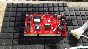
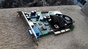
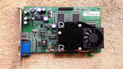
On the 22.12 2018, on a cold rainy day, I was at the local flea market. Few customers were present. Very little merchandise. Few vendors. Not one of the good days. Something made me get out of my comfortable home and go there. My gut was right, because that day I scored quite a few nice parts. I found my GUS ACE 1.1 / ADVANCED GRAVIS ULTRASOUND ACE VERSION 1.1 and a nice mATX motherboard MSI MS-6168 VER:2 plus a few other components.

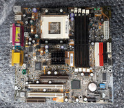
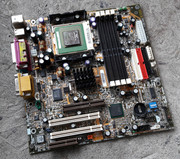
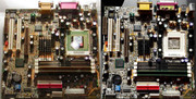
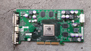
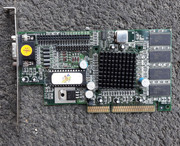
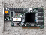
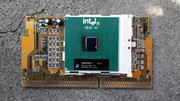
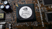
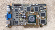
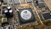
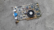
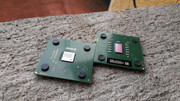
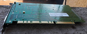
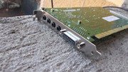
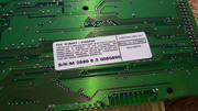
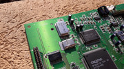
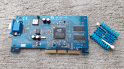
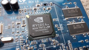
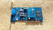
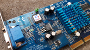
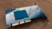
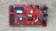
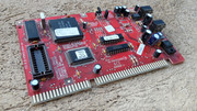
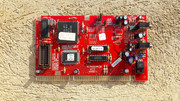
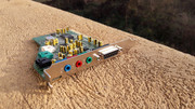
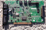
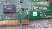
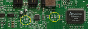
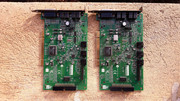
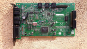
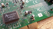
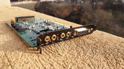
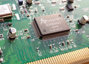
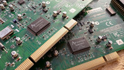
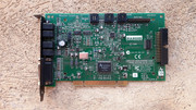
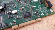
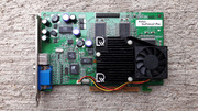
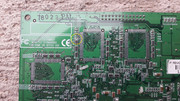
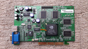
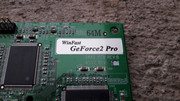
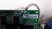
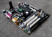
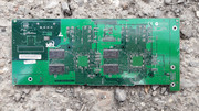
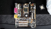
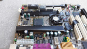
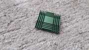
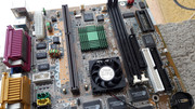
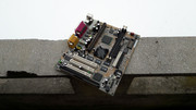
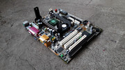
Depending of the revision number, the MS-6168 motherboard, can be equipped with a 440ZX or a 440BX chipset and it accommodates Slot 1 Intel Celeron/Pentium II/III CPUs. Nothing special you might say. What really stands out about this particular board is the 3dfx VooDoo 3 2000 onboard chip. Onboard? YES! ONBOARD! It can have 8MB or 16MB of video memory. In my case, the MS-6168 is Rev: 2.0 and it has a 440ZX/V3 2000 8MB. This model was used by Packard Bell in a series of desktops and it has the code name: Packard Bell Bora Pro. A must for 3dfx collectors!

CCI14012019.jpg CCI14012019-0001.jpg

You see, a few months before I found my MS-6168, I watched a few pictures on the internet and I said to myself that it will take quite some time before I was going to get my grabby hands on one. I was quite surprised when I found it at the local flea market. What were the odds?!?!?

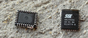
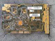
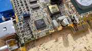
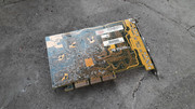
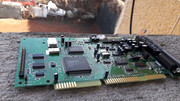
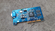
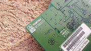
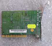
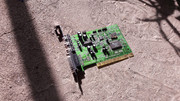
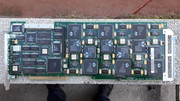
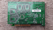
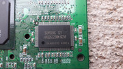
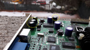
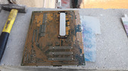
My MS-6168 was resting on a dirty tarp. The four Etrontech memory chips caught my eye and I took it my hands. I looked closely at it and soon I knew what it was. I composed myself and I asked casually how much is it. 2.2 EUROS! OK! MINE ALL MINE! NO BRAINER!

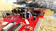
The motherboard had some damage, swollen capacitors and a few other problems. I didnt care about these downsides as I was quite happy to have an MS-6168. Something was telling me that everything will be alright.

A friggin' MS-6168! F@#!ING AWESOME!!!

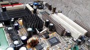
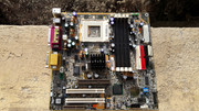
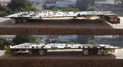
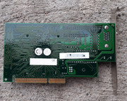
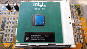
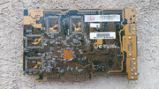
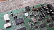
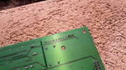
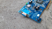
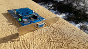
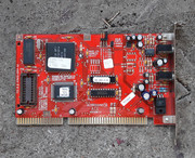
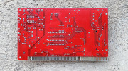
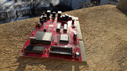
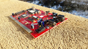
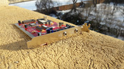
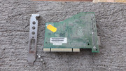
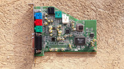
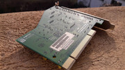
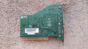
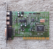
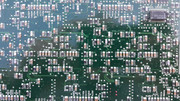
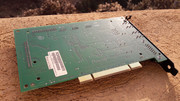
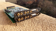
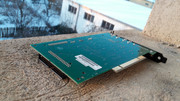
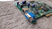
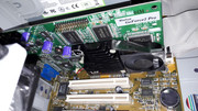
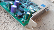
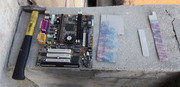
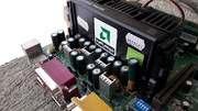
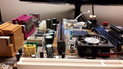
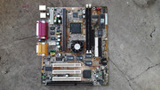
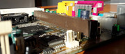
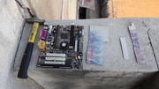
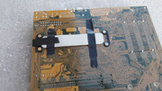
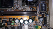
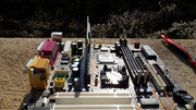
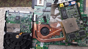
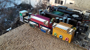
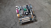
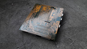
Let's see how "the wonder" looked when I bought it.

MS6168-V2-01.jpg

On a first glance you might say that it's not so bad. Right...

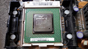
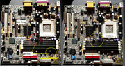
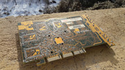
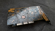
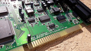
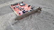
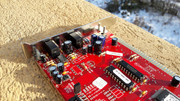
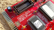
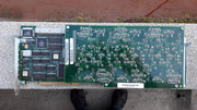
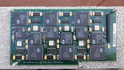
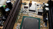
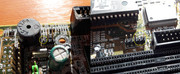
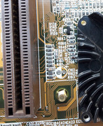
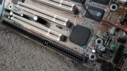
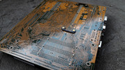
On 23.12.2018 I took the motherboard form its box and I performed a thorough examination. I removed the CPU plastic supporting arms system so that I could have a clear image of the area.

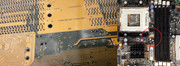
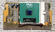
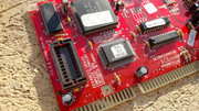
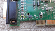
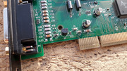
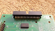
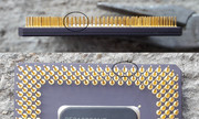
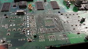
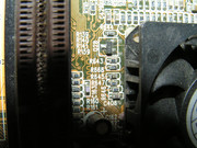
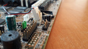
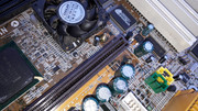
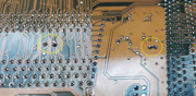
Right off the bat I saw that the CPU slot is crooked and a few pins were out of place.

MS6168-V2-02.jpg

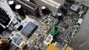
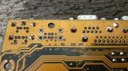
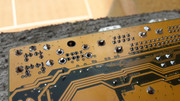
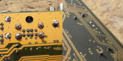
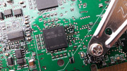
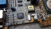
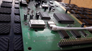
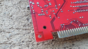
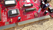
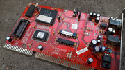
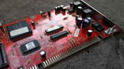
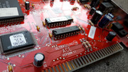
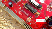
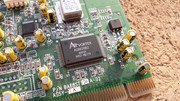
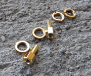
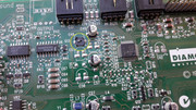
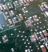
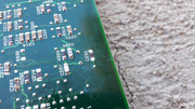
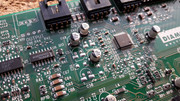
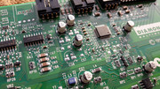
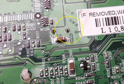
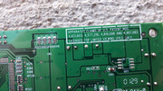
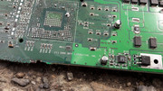
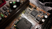
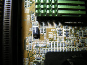
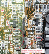
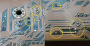
The CPU slot matter didn't faze me too much as what was worse was yet to come...5 SMD resistors with unknown specs together with 7 ceramic capacitors, were missing from the PCB. Massive force was used to remove the CPU from its slot and what was left behind was just carnage. One of the arms of the CPU support system was MIA. The NB Heatsink was also missing. You could still see the shreds from the thermal pad that was used to fix the heatsink.

MS6168-V2-03.jpg MS6168-V2-04.jpg

I had plenty of ceramic capacitors as I keep many donor parts. The SMD resistors were the real problem. I didnt know their specs. I also knew that it will be a PITA to solder them with what I had available. To make matters worse, the space was limited and I could solder just from one side. I left this headache for later.

Hours of internet searches have returned no information in regard to the specs of the SMD resistors . Low resolution, fuzzy pictures...what was I expecting after almost 20 years...

In the end I asked the help of two users of this forum: dionb and havli. (Thanks a heap for both of you!) I knew that they had a few MS-6168 motherboards. Both of them gave me a swift reply. dionb send me the pictures faster but his camera was broken and the phone pictures werent too sharp. havli told me that he will send me the pictures I need and even extra ones if they are required.

After these first steps taken towards the recovery of the MS-6168 I enjoyed a great Christmas without seeing any piece of HW. 😁

On 28.12.2019 I received the pictures from havli.

pict0084r1iwd.jpg pict00850net7.jpg

Now I had all the missing pieces of the puzzle. I knew what I had to do and I was confident that I can pull this off. My objective was the complete recovery of the MS-6168. GO BIG or GO HOME!

On 01.01.2019 I had some work to do where I keep my parts and I also had a few hours available for the MS-6168.

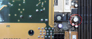
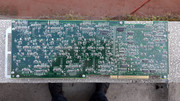
I recovered form the PCB, a ceramic capacitor and a 18A resistor. I didnt know from where the resistor came but I fished it near R647 where it was hanging by a thread. Later I found out that it came from the R648 position and not from R647. More about this will be presented later.

MS6168-V2-05.jpg

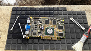
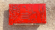
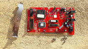
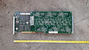
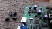
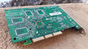
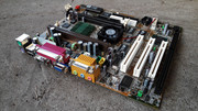
I took a few pictures before I started the work on the MS-6168.

MS6168-V2-06.jpg MS6168-V2-07.jpg MS6168-V2-08.jpg MS6168-V2-09.jpg

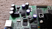
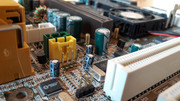
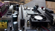
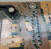
Other problems have been evaluated.

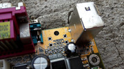
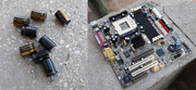
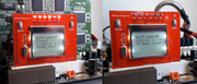
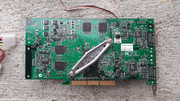
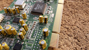
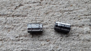
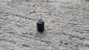
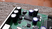
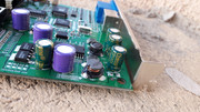
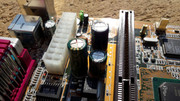
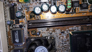
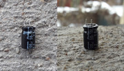
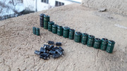
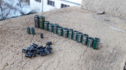
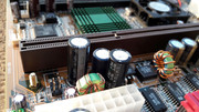
* High quality CHHSI electrolytic capacitors lay dead on the PCB. BAD CAPS ERA IN ALL ITS GLORY!!!
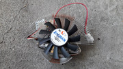
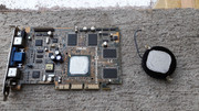
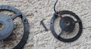
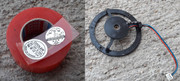
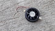
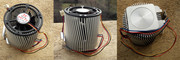
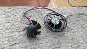
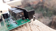
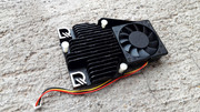
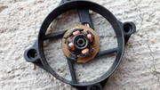
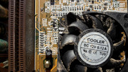
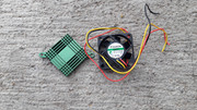
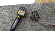
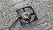
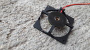
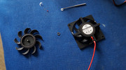
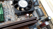
* The fan had a broken frame. The V3 2000 heatsink had a few broken fins.
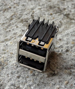
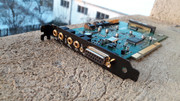
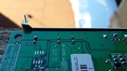
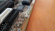
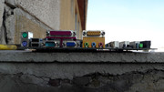
* A couple of pins for various connectors that look like Front Panel Pins were torn.
* Broken CR2032 socket
* Misc bent elements on the board
* Missing CD-IN socket

MS6168-V2-10.jpg MS6168-V2-11.jpg MS6168-V2-12.jpg MS6168-V2-13.jpg MS6168-V2-14.jpg MS6168-V2-15.jpg MS6168-V2-16.jpg MS6168-V2-17.jpg MS6168-V2-18.jpg MS6168-V2-19.jpg MS6168-V2-20.jpg

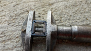
From all the problems that this board had, ONE was more pressing. The bent CPU slot. If the slot was bye bye, the rest was for nothing.

I tried to push the slot back into position by using the force of my hands. FAT CHANCE! It didn't budge and it just showed me the middle finger while it laughed at me.

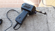
Hmm... this is a job for THE HAMMER!...I said to myself.

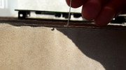
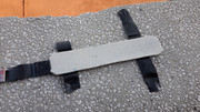
To avoid scratching or cracking the CPU slot and to prevent damage to the PCB or other parts I used some dense/thick cardboard.

I cut two strips that I placed on top and under the CPU slot to avoid damage. I fixed them with electrical tape.

I positioned the motherboard on a bigger piece of dense/thick cardboard and I started hammering.

HOLD YOUR HORSES!!! When I said hammering I didnt mean hitting the board with force as I just lifted the hammer about 5 cm from the board and I let if fall in a controlled manner. The weight of the hammer, correctly applied, did all the work. I didnt have to use myself too much.

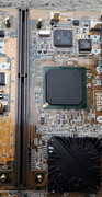
A few moments later the CPU slot was back in its place and you couldn't tell that it had a problem.

MS6168-V2-21.jpg MS6168-V2-22.jpg MS6168-V2-23.jpg MS6168-V2-24.jpg MS6168-V2-25.jpg

Glad that I sorted the CPU slot I removed the cardboard strips. Immediately I saw the pins that were out of their position.

MS6168-V2-26.jpg MS6168-V2-27.jpg

They didn't look to well... I said to myself that maybe it would've been better to put them into their place before I started the process of straightening the CPU slot...too late now...

I took a fine needle and I pressed gently on the CPU pins that were out of their position. Almost by magic, they made ping, ping, ping, ping and were back in their place. It seemed that it was better to straighten the CPU slot and then return the pins into their position! AWESOME!!!

MS6168-V2-28.jpg MS6168-V2-29.jpg

The pins that have been returned into their position didnt have and ideal shape. I used a credit card and a caseless slot 1 CPU to return them to factory spec. It didnt make sense to put them through additional stress by using the needle. What was important it was that they made good contact with the pins of the CPU.

MS6168-V2-30.jpg MS6168-V2-31.jpg MS6168-V2-32.jpg MS6168-V2-33.jpg MS6168-V2-34.jpg MS6168-V2-35.jpg

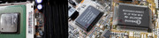
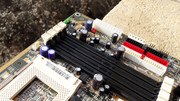
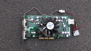
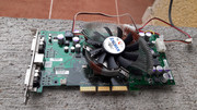
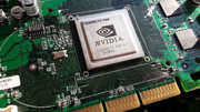
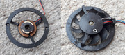
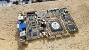
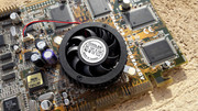
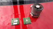
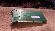
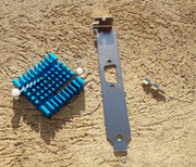
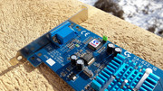
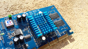
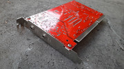
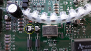
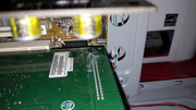
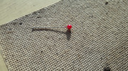
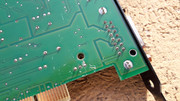
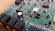
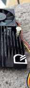
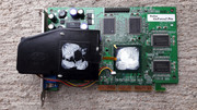
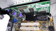
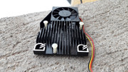
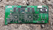
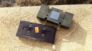
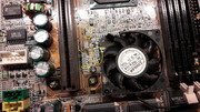
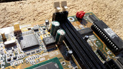
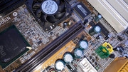
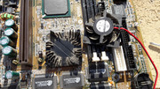
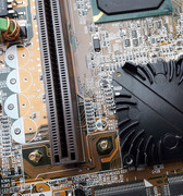
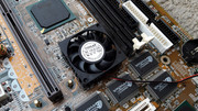
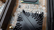
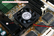
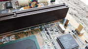
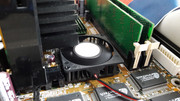
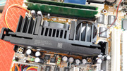
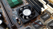
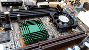
After I resolved the matter of the CPU slot I turned my attention towards the cooling of the VooDoo 3 2000 chip.

Not looking too good...

MS6168-V2-36.jpg

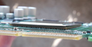
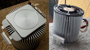
I already had some AKASA thermal adhesive pad and a replacement heatsink for the NB that looked just like the original. I bought the heatsink from the flea market, some time ago, thinking that I might need it. GOOD CALL!
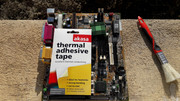
MS6168-V2-37.jpg

A tight fit!

MS6168-V2-38.jpg

So ended the day of 01.01.2019. Success all around!

I must underline that I didnt know if the MS-6168 was alive. What it is certain is that I didnt even think about faillure. The board was alive and kicking!. Case closed.

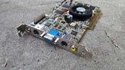
The year 2019 started on a high note in regard to the "Old School" HW. Eventually, between 03.01.2019-17.01.2019 I managed to return the MS-6168 to its former glory and I might even say that now it is better than new.

Once I got rid of the problems of the CPU slot, I tackled the remaining problems one by one and I solved each one of them. I knew that all could be fixed with patience and some skill.

I looked closely at the pictures I received. The matter of the ceramic capacitors and SMD resistors had to be dealt with.

MS6168-V2-39.jpg MS6168-V2-40.jpg

I couldn't buy the required SMD resistors as the minimum order is measured by tens or hundreds of pieces so I had to find them on my donor boards.

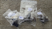
The detective work took some time but the results were great. All the missing bits were in my possession.

MS6168-V2-41.jpg

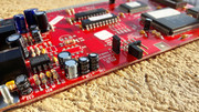
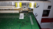
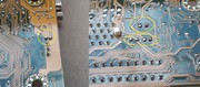
I used my 15W soldering iron and I managed to solder the 5 SMD resistors and 7 ceramic capacitors that were missing.

The transplant of the SMD components took some skill. I dont have a hot air station and all went at a snail's pace. If in the case of the ceramic capacitors I could mess up, in the case of the SMD resistors I had no space to maneuvre as they weren't too many to be had. All in all it was a stressful operation.

The final results were encouraging. At that time I thought that I solved the problem of the SMD resistors and ceramic capacitors. Later we will see that it wasnt so.

MS6168-V2-42.jpg MS6168-V2-43.jpg

The problem was represented by the 18A resistor which, based on the pictures I took of my MS-6168, had been soldered on the R647 position when it should've been placed on the R648 position. To make matters worse, because the 18A resistor was torn from the PCB, the solder didn't adhere to one of the ends, sign that the casing was damaged. This aspect remained in my mind and made me come back to this matter. NOTE: It is paramount to be pay attention to signs that something might be wrong even if you are certain that you did something correctly. Some signs must not be ignored. Usually I keep these pieces of information in a part of my mind and I come back to them later. It's not good to go in head first because you have more to loose if you do soo. Been there done that...

MS6168-V2-44.jpg

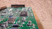
At that time I thought that "I fixed" the matter of the ceramic capcitors and the SMD resistors so I started the work on the cooling of the V3 2000 chip and NB.

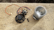
I prepared the replacement NB heatsink and I played with the ideea of replacing the fan on the V3 2000.

MS6168-V2-45.jpg

I also wanted to remove the heatsink from the V3 2000 but I gave up on this ideea because of the following reasons :

1. If the heatsink didnt fly off after three of its fins were torn off wouldn't I do more bad than good by removing it? The force needed might damage the solder balls of the V3 2000.
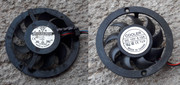
2. A feature of the MS-6168 is that cooling system on the V3-2000.
3. The space was tight and I didnt have a suitable replacement.

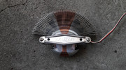
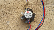
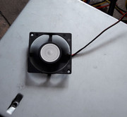
I cleaned up the fan, oiled the bearing and I powered it up. Surprisingly it still ran quiet.

I found a solution and I returned the fan to its former glory.

The missing part from the frame was made from a piece of plastic. The piece was held in place by superglue and reinforced with Poxipol.

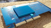
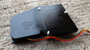
The scars of the missing fins from the V3 2000 heatsink were covered with black enamel paint.

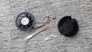
The NB heatsink wa prepared to be attached with AKASA thermal adhesive pad. I cut the parts where the push-pins entered and I covered the area with paint.

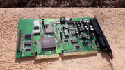
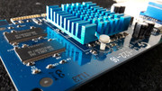
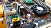
The final results were spectacular.

MS6168-V2-46.jpg MS6168-V2-47.jpg MS6168-V2-48.jpg MS6168-V2-49.jpg MS6168-V2-50.jpg MS6168-V2-51.jpg MS6168-V2-52.jpg MS6168-V2-53.jpg MS6168-V2-54.jpg MS6168-V2-55.jpg MS6168-V2-56.jpg MS6168-V2-57.jpg MS6168-V2-58.jpg MS6168-V2-59.jpg MS6168-V2-60.jpg

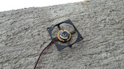
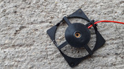
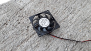
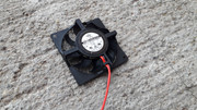
Because I wanted everything to be perfect I did some fine-tuning of the fan by adding a washer.. Now it was better than new.

MS6168-V2-61.jpg MS6168-V2-62.jpg

All the time I was occupied with the cooling of the V3 2000 one problem was still nagging me. The matter of the resistors still came into my mind, again and again.

I searched one more time on the Internet for pictures of MS-6168 boards. Eventually I found the pictures that I needed.

http://users.atw.hu/3dfx-nvidia/cards/msi_6168.htm

MS6168-V2-63.jpg

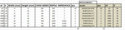
The resistors can have different tolerances form the value printed on them.10%, 5%, 2% si 1%. The most used ones have 1% and 5% tolerances.

Usually the resistors that have only numbers printed on them, have a tolerance of 5% and the ones that have numbers and letters printed on them, have a tolerance of 1%. (EIA-96)

I say usually because if you dont know the manufacturer you cannot check to see if they have a tolerance of 1% or 5%.

I used an online resistor calculator to find the value of the missing resistors.

http://kiloohm.info/smd3-resistor/101
http://kiloohm.info/eia96-resistor/18A

The pictures at my disposal made me come to the conclusion that in the end it didn't matter if the resistors had a tolerance of 1% or 5%. I couldn't find this exact information even if I wanted to. Besides, in one picture I had a 18A resistor and in another on the same exact spot was a 151 resistor. Probably, at the factory they used what was available.

I decided to remove the 18A resistor from R647 position which I didnt know from where it came from and solder a 101 resistor at R647 position, as it should be. At theR648 position I had a 151 resistor instead of a 18A resistor.

The 472 resistor was an exact replacement. I couldnt find a 822 resistor, no matter how much I searched, so, in the end, the chipped one that was persent on the PCB was my only shot to see if the motherboard is alive.

After a few soldering and desoldering operations, the protective/insulating layer from one of the resistors (151) was a little damaged. A multimeter test showed that it was alive so I left in place.

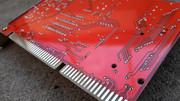
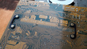
The 102 resistor was soldered with ease.

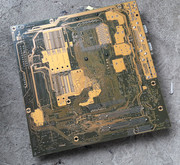
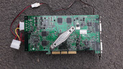
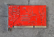
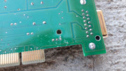
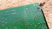
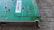
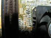
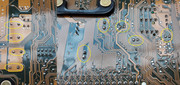
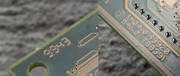
You can see the scratches left on the PCB when the SMD componets were sweeped. Miraculously the traces are still OK!

MS6168-V2-64.jpg

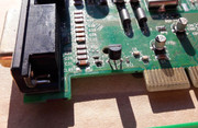
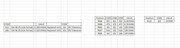
Notes in regard to the resistor values and position. These are different combinations I found in pictures of MS-6168 motherboards:

  • R646 822 822 822 8.2KOHMs
  • R668 472 472 472 4.7KOHMs
  • R645 101 101 101 100 OHMs
  • R647 01A 101 01A 100 OHMs
  • R646 151 151 18A 150 OHMs
  • R110 102 1KOHM

RESISTORS-01.jpg

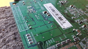
While I battled with the SMD resistors I also found some problems with a few of the ceramic capacitors that I soldered on the MS-6168. They didnt have the correct color code and had problems with the casing. I emproved the method by which I remove ceramic capacitors from donor boards and I replaced the ceramic capacitors that had problems.

The results were much better than the initial ones.

MS6168-V2-65.jpg

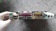
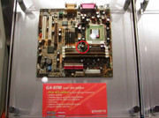
I soldered the new CR2032 socket which was taken from a Gigabyte GA-8TM motherbioard. The socket is an exact replacement.

The CD-IN socket was also taken from the GA-8TM.

The two torn pins were replaced with ones from a dead socket 3 motherboard.

I straightened all that was bent. I forgot to mention that along these repairs the MS-6168 was washed a few times with IPA99% but I guess you already knew that.

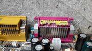
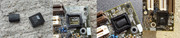
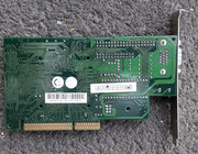
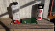
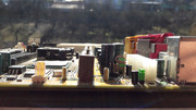
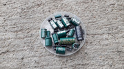
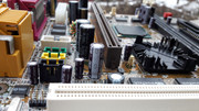
After this much work I had only one thing left to do. The replacement of the CHHSI electrolytic capacitors with something better.

I wanted to solder the same brand of capacitors top to bottom but in the end I bought what I could find at an online shop in my country. Also I had to buy some capacitors that weren't a direct replacement in regard to size. Some were taller by a few milimeters and some were a little wider. I spent for the caps around 13 EUROS. You will see that on my next big recap operation on the EPOX EP-7KXA, I ordered caps from a bigger supplier from Poland. All were ordered with the correct size. I also was able to buy all the caps with the same brand, PANASONIC FR all around.

I checked the specs of the new capacitors that I was about to solder and I saw that they were leaps and bounds above the CHHSI trash.

http://www.paullinebarger.net/DS/

No contest. CHHSI vs NICHICON UPW, RUBYCON YXJ, PANASONIC FC, RUBYCON ZL, PANASONIC FR. In total 35 caps have been replaced.

I did a few tests with various cards to see if the taller cap would reprezent a problem. All was ok. I didnt want to solder the cap on its side.

CAPS-01.jpg MS6168-V2-66.jpg MS6168-V2-67.jpg MS6168-V2-68.jpg MS6168-V2-69.jpg MS6168-V2-70.jpg

After a few hours of work all the caps have been soldered.

MS6168-V2-71.jpg MS6168-V2-72.jpg

My work was done as I did all that I could to ensure that the board was restored. There was only one thing left: to see if it is still alive and kicking.

Was all this effort for nothing? Will this board rise from its ashes?

After a final inspection has revealed that all was at 100% the board spent a night in a box and the following day was power up.

How was I able to restrain myself and not power up the board right away? I tell you how. By great will. Now I don't rush in like a fool and I take my sweet time before I press the button. 😁

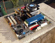
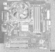
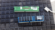
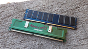
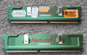
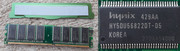
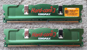
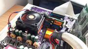
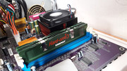
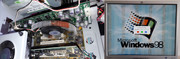
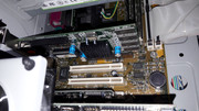
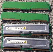
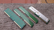
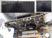
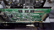
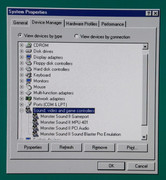
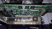
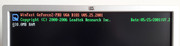
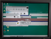
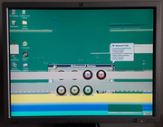
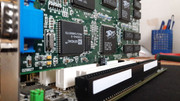
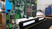
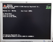
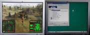
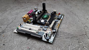
I installed a Pentium III 700MHz, 2x128MB=256MB RAM PC133, an ENERMAX PSU, etc and I started the MS-6168 after who knows how many years.

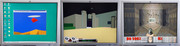
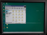
Did it work? He, He, He!!! You betcha!

MS6168-V2-73.jpg MS6168-V2-74.jpg MS6168-V2-75.jpg MS6168-V2-76.jpg MS6168-V2-77.jpg MS6168-V2-78.jpg MS6168-V2-79.jpg MS6168-V2-80.jpg MS6168-V2-81.jpg MS6168-V2-82.jpg MS6168-V2-83.jpg MS6168-V2-84.jpg MS6168-V2-85.jpg MS6168-V2-86.jpg MS6168-V2-87.jpg

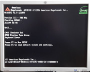
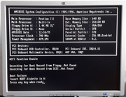
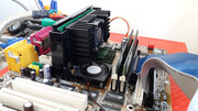
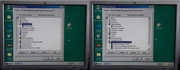
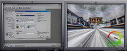
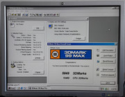
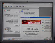
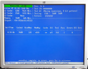
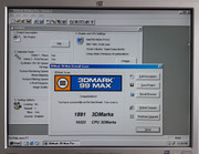
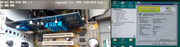
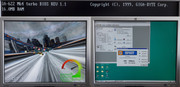
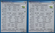
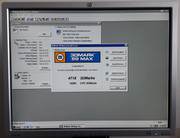
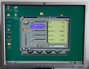
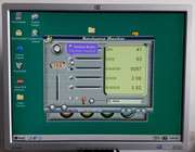
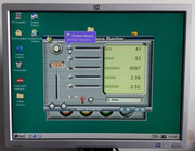
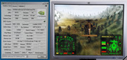
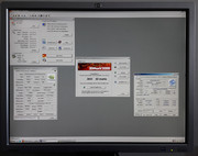
Surprisingly the V3 2000 143MHz 8MB onboard / MS-6168 440ZX / PIII-700MHz*100 / 256MB, scored 5849 points in 3dmark99 800x600, much better than V3 3000 166MHz 16MB / Luckystar 6VABX2 VIA693 / PIII-800MHz*100 / 384MB, which had a score of 4990 points. Also the CPU 3DMarks score on 440ZX/PIII-700MHz was 10469 points when the VIA693/PIII-800MHz scored 10554 points. 440ZX, brother of the 440BX was really something too. 440BX the legendary chipset. Hail for the KING!

See ya, wouldn't wanna to be ya!
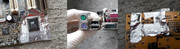
MS6168-V2-88.jpg MS6168-V2-89.jpg

The good stuff.

MS6168-V2-90.jpg MS6168-V2-91.jpg MS6168-V2-92.jpg MS6168-V2-93.jpg MS6168-V2-94.jpg MS6168-V2-95.jpg MS6168-V2-96.jpg MS6168-V2-97.jpg

The solder job on the electrolytic capacitors. For an operation of this scale, using a 100W solder gun with a modified tip, with little experience, using only the knowledge accumulated over the past years plus my common sense, I obtained decent results. 😁 An hour after I finished soldering the capacitors, the finger that was used to press the trigger started to go a little numb. The solder gun that I used is old and has little in regard to ergonomy. Two days I felt that numbness in my finger. By this you can understand the tension and the stress I was under while I performed this operation. It took me a while to understand that the numbness was from the force I pressed the trigger while all that was necessary was just a slight touch to engage the contact. At first I thought that I burned my finger but it wasnt the case. I didnt want to damage something and because I was sunk into work I didnt feel what I was doing. My eyes were fixed on the spot were I placed the tip of the solder gun. One bad move and I could have more headaches. After this baptism by fire I know what I have to do and I can replace hundreds of caps with little effort. While I worked it became obvious that at some point I will have to buy a soldering/hot air station and the required soldering tips. I must say that I cut the terminals of the caps before I solder them. Each to his own I guess, if the method works. With a suitable soldering/hot air station I'm sure that I can do solder joints like the factory ones as this is my ultimate goal.

MS-6168-V2-98.jpg MS-6168-V2-99.jpg MS-6168-V2-100.jpg MS-6168-V2-101.jpg MS-6168-V2-102.jpg MS-6168-V2-103.jpg

Food for thought. http://capacitorlab.com/replacing-motherboard … pacitors-howto/
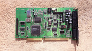
Better than new!

MS6168-V2-104.jpg MS6168-V2-105.jpg MS6168-V2-106.jpg MS6168-V2-107.jpg MS6168-V2-108.jpg MS6168-V2-109.jpg MS6168-V2-111.jpg MS6168-V2-112.jpg

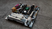
At the end of this story, you can see why I gave it the title THE PHOENIX.

The gist of this story is that: It could have turned out differently, I suppose. But it didn't. I'm so glad that this board is alive. It makes for a great story too! 😁

Looking back I can say that all the effort has paid off. Who would've thought that I would find this board at the local flea market and who would've accepted to go all in without knowing if the board is alive? Sometimes I reckon that it is better to shoot first and ask questions later. 😁

The knowledge obtained here was put to good use in the recovery of the EPOX EP-7KXA motherboard, which incidentally, will be featured in the next episode. 😁

gallery: https://postimg.cc/gallery/3bdnbqgp4/

More later.

Reply 479 of 844, by Robert B

User metadata
Rank Oldbie
Rank
Oldbie

Bad day at the flea market today.....I found a 3dfx VooDoo 5 5500 AGP for little over 1 EURO...

FM23032019-01.jpg FM23032019-02.jpg FM23032019-03.jpg FM23032019-04.jpg FM23032019-05.jpg FM23032019-06.jpg FM23032019-07.jpg

I also found a Medion GF4 MX460. Back in the day I had a GF4 MX460 from Gainward. The MX460 doesn't pop up too often so I bought it. The price was trivial and I removed it from a Medion P4 box.

FM23032019-08.jpg FM23032019-09.jpg

Next episode in the works. My first KX133 motherboard. EPOX EP-7KXA V.04

In the EPOX EP-7KXA episode, I grab my head with both hands when I see the capacitors, I have my share of surprises and because I heard that it can be done, I also change some grease. 😁

All of this and much more only in the next episode. 😁

PRW-EP-7-KXA16.jpg PRW-EP-7-KXA17.jpg PRW-EP-7-KXA18.jpg

More later.