Reply 140 of 1184, by maxtherabbit
Rank
l33t
- Rank
- l33t
wrote:How do you suppose they did this?
A reflow oven
wrote:How do you suppose they did this?
A reflow oven
LOL! Well, what did you think of the hand assembly? It seems to have gone ignored and I've been wondering if you are trying to talk yourself out of the PCB design. You don't have to do it. Is it a bit too complex for you?
You can even use male-female single row machine pin for the top PGA168 which would make it possible to solder the opposing end of the PCB's for most or all the pins.
Plan your life wisely, you'll be dead before you know it.
wrote:🤣! Well, what did you think of the hand assembly? It seems to have gone ignored and I've been wondering if you are trying to talk yourself out of the PCB design. You don't have to do it. Is it a bit too complex for you?
You can even use male-female single row machine pin for the top PGA168 which would make it possible to solder the opposing end of the PCB's for most or all the pins.
I'm actually trying to talk myself into doing it because it sounds like a cool project, but the reality check part of my brain keeps screaming at me not to invest hours of design time into something that:
1) is incredibly niche
2) will be impossible to hand solder cleanly - yes, you might be able to ghetto rig it by ripping the plastic supports off the pin headers but come on it's gonna be nasty
3) will still probably be no better than the combination of interposer + gainbury that you already tried and disappoint you
I'm trying to get psyched to do it so I could build one myself, but when I think about what would go into hand assembling one if I were to make the sockets concentric like you want, it just seems miserable and unfun
hmmmm... might be best to leave it to someone with more design experience and dedicated enthusiasm for the project then. If it doesn't end up working out well, I wouldn't want you to feel disappointed or that you've wasted time. Ideally, the person who draws up the design should feel indifferent towards to the final outcome. The joy is the journey and the fun is in its difficulty. If you are having to talk yourself into it, then this probably is not for you.
You commented that you think this project is incredibly niche. Yup, sure is! But not any more than the native PS/2 KBC adaption that you replicated. I believe there will be an approximately equal audience for both, assuming they are functional. Though, for the native PS/2 KBC adaption, it not fitting under a standard ISA card limits the application, while the less beautiful approach still fits under an inserted ISA card. Point being - sometimes beauty needs to be sacrificed for function or versatility. These will never be under mass production, nor be visible as floor units at a store. When the prototype is inserted into the motherboard, and the CPU is inserted into the prototype, you won't see the imperfect soldering work.
The SXL2-66 + Gainbery + Improve-It SXL adapter worked fine at 66 MHz and for most [all?] people, this is good enough. I think there are only 3 people out there with a working Evergreen SXL2-66 QFP144/PGA132 upgrade (plus a few CPU collectors). This production adapter doesn't work on all motherboards at 80 MHz. In the board I currently have it installed in, it maxes out at 66.7 MHz, while others worked at 80 MHz. Even at 66 MHz, this prototype would make for the fastest stable 386 upgrade (non-486 based) and I do not believe that the inability for it to run at 80 MHz would be a limiting factor for anyone. And there is always the 70-75 MHz range to play with :)
The lack of symmetry on the Gainbery + Improve-It adapter made it difficult to install on some of my motherboards. I had to stack up PGA-132 sockets to meet clearance with some other board components, an ISA slot if I recall right.
Plan your life wisely, you'll be dead before you know it.
One thought I have is to use two PCBs. Bottom socket connects to one, top socket to another and the two are joined by 1.27mm pitch pin headers at the perimeter, it shouldn't increase overall length of the traces too much and you could put a number of bypass caps on the top board too under the CPU area or even a full on regulator. This should be quite doable.
If I had one of these CPUs and a stable 386 board (my current main is acting weird for the time being) I'd begin right now 🤣
T-04YBSC, a new YMF71x based sound card & Official VOGONS thread about it
Newly made 4MB 60ns 30pin SIMMs ~
mida sa loed ? nagunii aru ei saa 😜
wrote:hmmmm... might be best to leave it to someone with more design experience and dedicated enthusiasm for the project then. If it doesn't end up working out well, I wouldn't want you to feel disappointed or that you've wasted time. Ideally, the person who draws up the design should feel indifferent towards to the final outcome. The joy is the journey and the fun is in its difficulty. If you are having to talk yourself into it, then this probably is not for you.
🤣 ok good luck finding that guy who will do it but still somehow not care about the results
I am 100% NOT a "life is about the journey" guy - only results matter to me
The PS/2 interposer is also kinda niche sure, but every 286-486 motherboard out there could potentially use it. If height is an issue, you could omit the socket and trim the headers down to get it to fit. The major difference though is that I am actually personally using it, so I was able to produce a meaningful result to justify my work.
wrote:One thought I have is to use two PCBs. Bottom socket connects to one, top socket to another and the two are joined by 1.27mm pitch pin headers at the perimeter, it shouldn't increase overall length of the traces too much and you could put a number of bypass caps on the top board too under the CPU area or even a full on regulator. This should be quite doable.
If I had one of these CPUs and a stable 386 board (my current main is acting weird for the time being) I'd begin right now 🤣
I actually really like this idea. It would also help with the routing tremendously.
If I can conceptualize a clear path to victory in my mind, I'm down to get started. But I'm definitely not jumping in head first to "enjoy" the journey. Journeys suck, I'm about destinations
wrote:Journeys suck, I'm about destinations
lol - we're all dead in the end. But if you are content with that mindset at this stage in your life, there's still plenty of journey left until you're dead.
Tiido - I'll think about this in the days to follow. We managed to convince a babysitter to come today (only 1 in 20 will even come back) and I'm going to go enjoy my journey to the beach. First time in a year.
EDIT: As of this evening, our babysitter quit! She lasted for 4 visits, which wasn't too bad.
Plan your life wisely, you'll be dead before you know it.
I've attached the latest version of the interposer last I worked on it I had fixed a few error in the pin mappings in teh schematic so I think that is all right now.
I think it would probably make sense to go with a smaller regulator than what I have on here now unless the board were to stick out past the socket more... as it is a bit cramped. Probably 805 resistors make the most sense still small enough to hand solder but not to big to get in the way as some of the other suggested options probably are.
The more I've looked at it I think this needs to be at least a 4 layer board. with probably power zones on the 2 internal layers.
The files were last updated with KiCad 5. Note I have 3d models on my end for the sockets that you may not have the intention is to reflow them on with low temp solder paste like this https://www.amazon.com/Solder-Bi57-6-No-Clean … MTJV2191AVVTKR2
Indivitual SMT pins might work on the bottom... load them into a socket then reflow, the top side would just be a regular socket reflowed on. This aspect is fairly important as if any pins were to go through the board it would make it far too complex to route easily. Also anything you put on the board has a good chance of being in the way...
BTW instead of doing 2 PCBs it probably makes sense to go for 4 or even 6 layers as at 6 layers the cost is still only about $7 per board for the board itself... 10 boards = $75 100 boards = $150 if only economy of scale were practical in this case 10 boards is probably more realistic.... four layers is much cheaper at $1.3 per board. Note the board is currently 50x50mm.
Thanks a lot for attaching this. In your opinion, is it ready to order? Were there any recommendations which you weren't able to implement? I personally won't have opportunity to look at this for some time. Would you be willing to provide some 2D and 3D views? I'll try to get KiCAD 5 installed sometime this month, assuming it still installs on XP. I've been spending most of my time with some frusturating VS440FX and socket 4 boards and, worst of all, trying to find a baby sitter willing to watch our 3 rowdy kids for long hours. This seems to be a lost art for the current youth, at least in our location.
Plan your life wisely, you'll be dead before you know it.
wrote:Thanks a lot for attaching this. In your opinion, is it ready to order? Were there any recommendations which you weren't able to implement? I personally won't have opportunity to look at this for some time. Would you be willing to provide some 2D and 3D views? I'll try to get KiCAD 5 installed sometime this month, assuming it still installs on XP. I've been spending most of my time with some frusturating VS440FX and socket 4 boards and, worst of all, trying to find a baby sitter willing to watch our 3 rowdy kids for long hours. This seems to be a lost art for the current youth, at least in our location.
Ah well if you opened it up in kicad that it isnt' routed... so no it isn't ready.
Most of the work I've done is in the schematic and the VRM there isn't done and needs work. Btw KiCad 3 is unlikely to work on XP it might work... but I wouldnt' count on it and even if it does the 3D viewer will be broken. I would strongly suggest upgrading to at least windows 7 or you are going to be out of luck even with open source software these days as the toolchain support for XP have been neglected for years.
I've been playing around with the inboard in the Compaq Portable I got... I think it's a base model of the card seems to only have 256k on it I imagine that is one row of SRAMs... so I'll have to get some of those to get it up to 1MB. Also, what ever happened to that guy that was working on a DIY piggybackboard for the Inboard.. IIRC he had killed an inboard with a prototype somehow so I'd rather pick his brain than kill my own! You would think it would be easy enough to trace out what is what on the memory expansion header... Eventually I want to get the fastest CPU I can working via interposer in my XT and one of my portables also plan on making a small EGA adapter board to compaq portable for the Video7 VEGA card... and also plan on making a hyperstation 30 3d printed case... and so on 🤣.
OK. So do you think you'll not be proceeding with the PCB? Perhaps someone else will pick it up at some point.
Upgrading WinXP is on my list, but time hasn't been on my side recently. And Windows 7 is nearing EOL, so I've been meaning to get Win10, but, time. Also, I couldn't pick one of my kids last week - I went to startup my 1970's Benz from the garage and the clutch was at the floor, and some brake fluid puddles under it as I tried to start it anyway. I had replaced the master and slave clutch cylinders in 2014 and didn't think there would be a problem so soon. So more crap to work on that has priority.
I'm not familiar with the Inboard. Sorry. I did have one of those Compaq briefcase computers from the 80's at one point, but I let it go.
Plan your life wisely, you'll be dead before you know it.
IMO tiido still has the right idea with 2 PCBs
yeah it might increase the board cost a little but that's easily worth it relative to having to deal with reflowing heinous SMD PGA sockets and pin headers. it would also make routing much easier
thanks for posting the kicad schematics and symbols - I might take a crack at it now
Best of luck.
Hope trace length isn't an issue with the paired PCB approach. If it works at 66 MHz, it is still a success. 80 MHz is a bonus.
Plan your life wisely, you'll be dead before you know it.
wrote:IMO tiido still has the right idea with 2 PCBs
yeah it might increase the board cost a little but that's easily worth it relative to having to deal with reflowing heinous SMD PGA sockets and pin headers. it would also make routing much easier
thanks for posting the kicad schematics and symbols - I might take a crack at it now
Nah thats nonsense... nobody else has ever done, EVER that for a reason. It's just more work... you'd always just use a 4-6 layer board instead. Reflowing the BGA packages is trivial... you should be able to do it with a hot plate or hot air gun relatively easily.
Also I do intend to continue with my design... it just isn't one of my priorities it's a hobby after all.
wrote:wrote:IMO tiido still has the right idea with 2 PCBs
yeah it might increase the board cost a little but that's easily worth it relative to having to deal with reflowing heinous SMD PGA sockets and pin headers. it would also make routing much easier
thanks for posting the kicad schematics and symbols - I might take a crack at it now
Nah thats nonsense... nobody else has ever done, EVER that for a reason. It's just more work... you'd always just use a 4-6 layer board instead. Reflowing the BGA packages is trivial... you should be able to do it with a hot plate or hot air gun relatively easily.
Also I do intend to continue with my design... it just isn't one of my priorities it's a hobby after all.
OK then good luck
How about two designs - see which one works best?
Plan your life wisely, you'll be dead before you know it.
FYI, some collectors on CPU-World are talking about a group buy to for the TI486SXL2-66 PGA168 chips from the westfloridacomponents distributor. There are currently 35 remaining at $16.50 each ($14.50 at 10+ quantity). I thought it appropriate to let anyone following this thread know ahead of time in case you wanted to order these SXL2-66 chips NOS from that distributor 1 week before the group buy is announced, after which, all of these chips could be sold out. It is possible that westflorida has another supply, and possibly not.
But... I have updated my post here Re: Custom interposer module for TI486SXL2-66 PGA168 to PGA132 - HELP! to include the other reseller of these CPUs. They appear to have 400 of them, but they are $19.50 (no photo though).
Plan your life wisely, you'll be dead before you know it.
A CPU collector sent me some photos of another SXL2-66 upgrade, this time PGA-168 with VRM. This is what we're trying to replicate, minus the unnecessary extra circuitry. This adapter uses an EZ1086CM as the VRM. I have never seen one of these adapters in person or in photograph until now, so I suspect it is exceedingly rare.
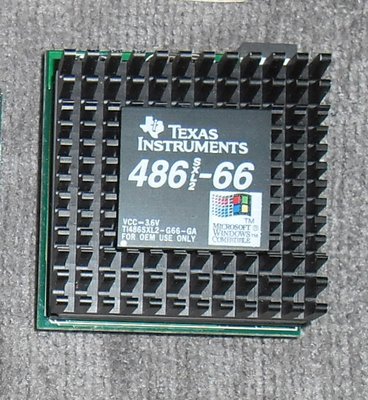
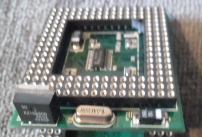
Plan your life wisely, you'll be dead before you know it.
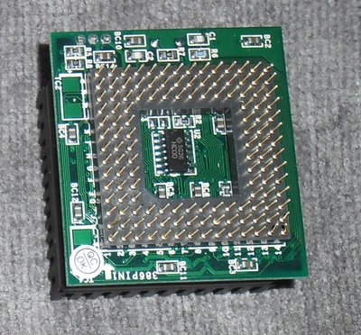
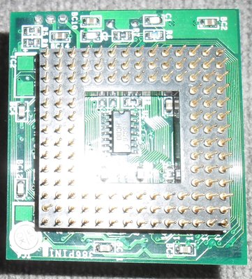
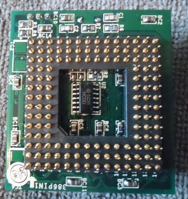
Here are some side-by-side shots of the three known SXL2-66 adapters. Interesting how one manufacture chose to centre the PGA, while another offset it to the corner. The offset one does not come with a VRM.
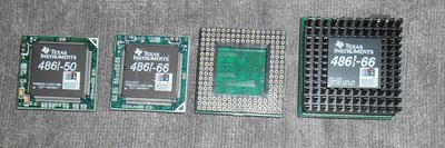
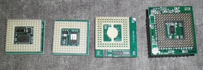
Plan your life wisely, you'll be dead before you know it.
neat!
It is a mistake to think you can solve any major problems just with potatoes.


