Jo22 wrote on 2021-01-10, 07:04:
mkarcher wrote on 2021-01-09, 19:32:
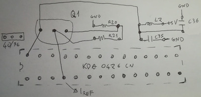
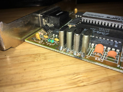
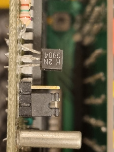
I can give you a hint about Q1: I checked three ISA graphics card with a classic 28-pin DIP RAMDAC. All of them have a three-terminal device near the RAMDAC, and it is labelled "Q1", although it is not a transistor, but a reference chip. It's a good thing that it is a reference chip, because you need a regulated current sink on that pin to get a good image. Two if the three cards a I checked use a TL431 reference chip. The connection is: Pin on one edge ("pin 3") to 5V (decoupled using an inductor), pin on the other edge ("pin 1") connected to pin 4 of the RAMDAC (Iref), a resistor between the pin 1 and pin 2, and another resistor between pin 2 and -12V (contact B7 on the ISA bus). The two resistors I mentioned will be R20 and R21 on your card.
Interesting. From what I remember, "Q" also refers to oscillators (quarz crystals; complete crystal oscillators are named "X" or "XTAL") or mixers . Sometimes "Q" also refers to transistors (though in my country, "T" is more often used for this).
I haven't seen Q for "quartz" yet, at least I don't remember. I know X or Y both for crystals and crystal oscillator packages, though. Sometimes the oscillators also carry the generic "U" or "IC" marking for integrated circuits. I know Q mostly for transistors in english schematics, whereas german schematics tend to use T.
Jo22 wrote on 2021-01-10, 07:04:Or more precisely, here, "Q" refers to transistors that act as a switch (digital), while "T" is used if a transformation happens […]
Show full quote
Or more precisely, here, "Q" refers to transistors that act as a switch (digital), while "T" is used if a transformation happens, like an amplification (analogue).
Though in practice, hobbysts here may simply use "T" anyway.
Edit: Seems there was a lot of confusion throughout the times.
In old schematics, transistors were als called "TR" or "V" (Germany), while transformers also had the "T" symbol. So yeah, it's really a mess. 😅
That's interesting. I don't remember any schematics that differentiated between switching transistors and amplification transistors in their symbols. And I would expect "TR" to be a transformer more likely than a transistor. The "V" is an anachronism, and is most likely rooted in "V"alve as a term for vacuum tubes that got replaced by semiconductor transistors.
Jo22 wrote on 2021-01-10, 07:04:
mkarcher wrote on 2021-01-09, 19:32:
If the resistors are as I described, a TL431 should do as replacement.
Oh well, so it might be a shunt device that acts similar to a z-diode? I didn't expect this. 😅
I expected ISA era devices would rather use big regulators in the size of mosfets or a 7805. I'm glad you got involved. 🙂
The VGA RAMDAC doesn't want a voltage refernce, it wants a current reference. If I understand the datasheet correctly, for a typical VGA design, you need to sink 8.8mA from pin 4 (Iref) to get correct RGB levels. The voltage at Iref is not clearly defined and might depend on temperature and be slightly different on different copies of the same chip. The datasheet for the KDA0476 shows a version with an adjustable negative voltage regulator used in current regulator configuration (they don't spell out which one to use, but I guess the LM337 variant in TO92 case would be fine), and the third ISA VGA card I looked at uses a LM334 current reference.
The TL431 (and all of its many copy cats like LM431 and so on) is likely a lot cheaper. The circuit works like this: There is a reference resistor between the reference input and the anode (remember, the Z diode has the anode at the negative end!). The reference input is also connected to the Iref pin. The TL431 is high impedance at the reference input, so the whole current from Iref passes through the reference resistor. The reference resistor is chosen such that the desired current causes a drop of 2.45 volts on the reference resistor. If the current from Iref is too high, the TL431 starts conducting more current, so the voltage drop on the resistor between anode and -12V increases, so the voltage at the anode increases, so voltage (and current) on the reference resistor goes down. If the current from Iref is too low, the TL431 doesn't conduct any current from cathode to anode, the voltage at the anode goes down and thus the current over the reference resistor increases - this is how the regulation loop is closed in this circuit.
I wonder whether the vertical banding you see even on analog monitors (so it most likely isn't a sampling artifact there, although you might get a moiree between the dot clock and the shadow mask) might be caused by instability of this Iref regulator due to degraded caps. The voltage at Iref might be dependant on the color, so the step at the start of a line (from black blanking to background color) can be an excitation source that synchronizes the instability of the regulator to the horizontal frequency.
