VOGONS


Reply 20 of 63, by CalamityLime

User metadata
Rank Member
Rank
Member

Part 11: PSU Part 2

So, here we go, fitting a new atx power supply to an AT pc.

I looked around for other solutions, the cheap atx to at adapters were an option, the good one with -5 was not. You can use an older ATX supply with -5 but I have none and I don't know where to even get one. One person even recommend to fit the insides of a new psu into an AT body and solder in the wires.
I weighed my options and choose my own path.

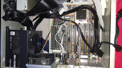
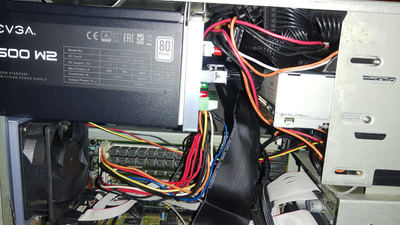
I looked around on amazon for a psu that could give out the required amps on 5v for not too much money and I found the EVGA 500 w2, 80+ white. The amps on the +5 and -12v matched the old Dell AT supply so I grabbed what one while it was on sale. I didn't want to gut it and put it inside the old dell case because I wanted to keep the warranty. So I picked up an ATX breakout board.
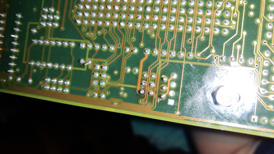
I cracked open the Dell psu and cut out all the wires I could.

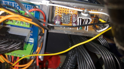
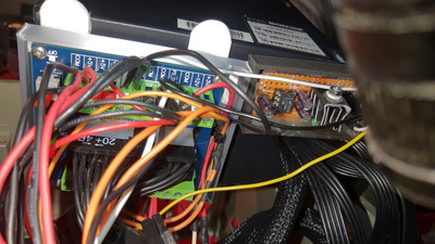
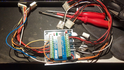
The breakout board arrived first so I wired the AT wires into the breakout board, plus a molex wire to give myself more molex wires. I designed and 3d printed a holder for the breakout board that sticks to the back of the PSU. STL linked.
I'm personally delighted I went with this solution since I can just tap into any of the PSU rails easily. It was a very tight fit but it fit and it worked a treat with a handy power button inside the case! I kept the old power switch to save me having to print out the CF card holder again.

Obviously this solution does not have -5volt but more on that in the next post.

Attachments

Be Happy, it's only going to get worse.
- Projects
Limes Strange 3D models
USB-2-232

Reply 21 of 63, by CalamityLime

User metadata
Rank Member
Rank
Member

Part 12: PSU Part 3.

That's well and good but that doesn't solve the -5volt problem. So I dug into my options to figure out what would work best for me.

Options:
Inverting Buck converter: The same thing used by the good atx to at adapter.
You can make your own for fairly cheap but it might be a bit bulky. Most buck chips are cheap and the datasheets include reference schematics for building your own inverting buck converter. You can get a "decent" bit of power out of them but to my understanding you only need a few milliamps.

7905 voltage regulator.
This would just connect to the -12v from the psu and convert it to -5. While it's a tidy little solution I decided against it because the -12 gives out so few milliamps that I didn't trust it. I'd also prefer to use the 12volt rail to keep it stable.

7805 + Charge pump
Ultimately I went with this solution. I picked a charge pump that claims to deliver 200millamps @ -5 volt, LTC1044. I paired that with an 7805 connected to 12v. Originally I was going to use a Buck converter to go from 12v to 6v, then LDO that down to 5V (which helps cut the noise of the switching) but 12v -> 5v @200 milliamps produces 1.4w of heat that a little heatsink can dissipate fairly easily. I'd expect to not draw more than 100milliamps so that cuts it down to less than 1W of heat. It's fairly compact with an inductor on the out to help cut the noise of the switching. Since the -5 is used mostly for sound cards, a low pass filter on the power going into the pc will help the noise.
Currently I don't have this connected up but I have the board made up, I have no sound card so I have no need for -5volt
I did go a little out of spec with the caps but I did that because I found that reference values produce noisey power.

If anyone knows a simple schematic builder, I'd be happy to draw out the circuit.

TBH, maybe take this post as a sign to get a good old atx supply with -5 built in.

Attachments

Be Happy, it's only going to get worse.
- Projects
Limes Strange 3D models
USB-2-232

Reply 22 of 63, by CalamityLime

User metadata
Rank Member
Rank
Member

Right, I think I'll pause there for the moment, I have to make some dinner and such.

There is more, including heatsinks, other processors and caps.

I hope you find this interesting! It's been a lot of fun. Thanks for reading.

Be Happy, it's only going to get worse.
- Projects
Limes Strange 3D models
USB-2-232

Reply 23 of 63, by Joseph_Joestar

User metadata
Rank l33t
Rank
l33t
CalamityLime wrote on 2021-07-23, 18:50:

That's well and good but that doesn't solve the -5volt problem.

You may find this interesting: Phil’s latest video - Voltage Blaster

PC#1: Pentium MMX 166 / Soyo SY-5BT / S3 Trio64V+ / Voodoo1 / YMF719 / AWE64 Gold / SC-155
PC#2: AthlonXP 2100+ / ECS K7VTA3 / Voodoo3 / Audigy2 / Vortex2
PC#3: Athlon64 3400+ / Asus K8V-MX / 5900XT / Audigy2
PC#4: i5-3570K / MSI Z77A-G43 / GTX 970 / X-Fi

Reply 24 of 63, by CalamityLime

User metadata
Rank Member
Rank
Member
Joseph_Joestar wrote on 2021-07-23, 18:59:
CalamityLime wrote on 2021-07-23, 18:50:

That's well and good but that doesn't solve the -5volt problem.

You may find this interesting: Phil’s latest video - Voltage Blaster

That makes sense to do. It is just taking the -12 pumping it through the 7905 to get -5 then injecting that back into the isa slot. I'm kinda surprised there are not more solutions like this though.
Thanks for pointing it out!

Be Happy, it's only going to get worse.
- Projects
Limes Strange 3D models
USB-2-232

Reply 25 of 63, by CalamityLime

User metadata
Rank Member
Rank
Member

Part 13: Plans for 3.3v.

By default the Soyo 25n2 does not support 3.3v but the p variant of the board does. Which thankfully means there is a blank spot for a voltage regulator.
I ordered a LM1084IT-3.3 regulator and an appropriate heat sink for the regulator. I went with a fixed output because the resistors for setting the voltage of a variable regulator were swapped so the output voltage of the regulator would be about 1.9v, rather than switch the resistors around I removed them and bridged the connection to ground.

I thought about running 3.3v direct from the psu but that felt like cheating.

So I bought an AMD dx4 100mhz from ebay, it arrived all nice and tidy with no bent pins, happy days. Installed the voltage regulator, tested the output to make sure it was okay, added the jumpers to switch between 5 and 3.3v cpus.
While I was at it I replaced most of the caps on the board and the two expansion cards that came with it. Even installed an extra filter cap for the -5 volt rail, for some reason the spot for that cap was unpopulated.
De-soldering the caps from the board was a pain to do. Sometimes the solder came out just fine and other times it just didn't want to come out. The expansion cards on the other hand were easy peasy.

Unfortunately the flux did not want to come off the board so I had to resort to washing it again with a little tooth brush. The same flux came off of the expansion cards without any issue. I guess the board felt like being a pain for that job.

After Letting the board dry for a while to make sure there was no liquid left over, I plopped in the dx4, set the voltage to 3.3, crossed my fingers and booted the machine. It have me a happy post beep and popped up saying that it's cpu is a dx2 100, which I thought was curious. Maybe it's a bios issue?
I ran a few benchmarks and there was indeed a difference. I couldn't let the pc on for too long because the CPU was getting too hot to touch. Next challenge, a heat sink.

PS: I didn't leave the solder on the back that bad, I noticed how bad it was in the photo and patched it up.

Attachments

Be Happy, it's only going to get worse.
- Projects
Limes Strange 3D models
USB-2-232

Reply 26 of 63, by CalamityLime

User metadata
Rank Member
Rank
Member

BTW, between messages I installed the -5v generator. It looks messier than I thought it would but it seems to work.
I don't have anything to test if the power is actually reaching the ISA slots or not.

Attachments

Be Happy, it's only going to get worse.
- Projects
Limes Strange 3D models
USB-2-232

Reply 27 of 63, by CalamityLime

User metadata
Rank Member
Rank
Member

Part 14: Heatsink

So because the 486dx4 wants a heatsink I had to figure out something to keep the CPU cool.
The dx2 has a heatsink stuck on there but I have no idea how to take it off, since it could be stuck down in several different ways, I'm reluctant to just yank it off.

I have seen it suggested to use thermal adhesive or superglue in a corner, things that are either permanent or would damage the ceramic on the chip. Which I really don't want. The old clip on style heatsinks for 486's are expensive even if they are missing clips. So I turned to ebay for a inspiration, I found a cheapish heatsink that claims to mount to a 486 and I bought it with intention to figure out the hard part later.

After it had arrived, I set to work finding a way to mount the heatsink to the cpu. After some iteration I managed to design and 3d print something that mounts to the chip, uses thermal paste, gives a really good mount and prints fine with petg plastic (I made test fits with orange pla)
I was over the moon with this mount I had made and the thing didn't fit in on my board because the socket had a leaver. I couldn't just cut the nut holders off of the sides of the harness because I would have to cut off three of them, ruining the mount.

I included the STLS in case they are useful for anyone here, feel free to use them.

So this is where I am now, how to keep the dx4 cool.
If anyone has any tips, let me know.

Attachments

Be Happy, it's only going to get worse.
- Projects
Limes Strange 3D models
USB-2-232

Reply 28 of 63, by jakethompson1

User metadata
Rank Oldbie
Rank
Oldbie
CalamityLime wrote on 2021-07-23, 23:03:

After Letting the board dry for a while to make sure there was no liquid left over, I plopped in the dx4, set the voltage to 3.3, crossed my fingers and booted the machine. It have me a happy post beep and popped up saying that it's cpu is a dx2 100, which I thought was curious. Maybe it's a bios issue?

Suspect you have a Standard Am486DX4 rather than an Enhanced one. The standard uses the same CPUID as a DX2. This should be a cosmetic issue, with the only exception that if you use autoconfiguration in the BIOS, it might think the board is running with a 50 MHz clock and set memory and cache timings more conservative than they need to be.

Have you noticed if the BIOS will let you set the year to 2021 or does it set it to 2094 on every reboot? That can be fixed.

My profile image has my own take with cooling. The heatsink is standard, the bracket 3D printed.

Reply 29 of 63, by CalamityLime

User metadata
Rank Member
Rank
Member
jakethompson1 wrote on 2021-07-24, 02:05:
Suspect you have a Standard Am486DX4 rather than an Enhanced one. The standard uses the same CPUID as a DX2. This should be a co […]
Show full quote
CalamityLime wrote on 2021-07-23, 23:03:

After Letting the board dry for a while to make sure there was no liquid left over, I plopped in the dx4, set the voltage to 3.3, crossed my fingers and booted the machine. It have me a happy post beep and popped up saying that it's cpu is a dx2 100, which I thought was curious. Maybe it's a bios issue?

Suspect you have a Standard Am486DX4 rather than an Enhanced one. The standard uses the same CPUID as a DX2. This should be a cosmetic issue, with the only exception that if you use autoconfiguration in the BIOS, it might think the board is running with a 50 MHz clock and set memory and cache timings more conservative than they need to be.

Have you noticed if the BIOS will let you set the year to 2021 or does it set it to 2094 on every reboot? That can be fixed.

My profile image has my own take with cooling. The heatsink is standard, the bracket 3D printed.

According to the boards manual there are jumpers for setting which CPU you're using, the DX2 66 and DX4 whatever use the same jumper settings.

The bios doesn't seem to have any issue with 2021 after a reboot from clearing cmos.
So after the cmos is cleared the year cannot pass over the millennium, just lets me change which year in the 1900's it is, after a reboot or just leaving it for a minute, it lets me set a year higher than the millennium and it keeps it no bother. I guessed it was a weird Y2K patch. I caught it doing that a few times, at first I thought the bios was old enough or cheap enough to not be Y2K compliant.
I don't have the means to image the bios chip so I can't send that on.

Thanks for the tip, I'm kind of tempted to sit the heatsink from the old dx2 in some IPA, just enough to go over the lip of the heatsink and get at whatever it holding it on there. Hopefully it's thermal tape which the ipa should loosen.

Be Happy, it's only going to get worse.
- Projects
Limes Strange 3D models
USB-2-232

Reply 30 of 63, by Chkcpu

User metadata
Rank Member
Rank
Member

I have this 09/26/94-SIS-85C471B/E/G-2C4I9S23-00 / REV .G2. BIOS in my collection and have attached it here.
This BIOS image was taken from a Soyo 25K2 board, and I have seen it on Soyo's 25JKL series as well. Like the 25N2, these boards all use the same SiS471 chipset.

I've checked this REV .G2. BIOS for CPU support and known Award BIOS bugs. This is what I found:
- Year 2094 bug
- 2GB Harddisk display limit bug (HDD's up to 8GB will work but the displayed size in the BIOS Setup and during POST is wrong for > 2GB drives, so this is a cosmetic bug)
- No support for Enhanced Am486Dx2/DX4, Am5x86-133, and Cyrix 5x86 CPUs.

Greetings, Jan.

Attachments

  • Filename
    Soyo-025N2-G2.zip
    File size
    44.34 KiB
    Downloads
    45 downloads
    File license
    Fair use/fair dealing exception
Last edited by Chkcpu on 2021-08-09, 20:17. Edited 1 time in total.

CPU Identification utility
The Unofficial K6-2+ / K6-III+ page

Reply 31 of 63, by Chkcpu

User metadata
Rank Member
Rank
Member

Hi CalamityLime,

In addition to my previous reply, I have some further BIOS info.

If you are looking for an updated Soyo 25K2/25N2 BIOS to fix the bugs I mentioned, I have one attached below.
It is a 11/28/95-SIS-85C471B/E/G-2C4I9S21-00 / REV. J.1 BIOS for the Soyo 25JKL series and I'm confident it will work on your 25N2 as well.

This 11/28/95 BIOS is milenium compliant, supports HDD's up to 8GB, and supports all enhanced Intel/AMD/Cyrix 486/5x86 CPU's including L1 cache WB mode.
Note that this BIOS only shows the “L1 cache: WB/WT” option in the BIOS Setup for the P24T and for Cyrix CPUs.
For the P24D (486DX2WB), Am486DX4WB and Am5x86, this 12/28/95 BIOS can detect if these CPUs are in WB mode and programs the chipset registers accordingly. It then hides the “L1 cache: WB/WT” option, because user interaction for this automatic function is not required.

I took this up-to-date SiS471G BIOS from a Gemlight board and carefully adapted it for these Soyo boards, including the default chipset register programming from the original REV .G2. BIOS.

Cheers.

Attachments

  • Filename
    Soyo_25JKL-J1_BIOS.zip
    File size
    45.22 KiB
    Downloads
    52 downloads
    File license
    Fair use/fair dealing exception

CPU Identification utility
The Unofficial K6-2+ / K6-III+ page

Reply 32 of 63, by CalamityLime

User metadata
Rank Member
Rank
Member
Chkcpu wrote on 2021-07-25, 18:01:
Hi CalamityLime, […]
Show full quote

Hi CalamityLime,

In addition to my previous reply, I have some further BIOS info.

If you are looking for an updated Soyo 25K2/25N2 BIOS to fix the bugs I mentioned, I have one attached below.
It is a 11/28/95-SIS-85C471B/E/G-2C4I9S21-00 / REV. J.1 BIOS for the Soyo 25JKL series and I'm confident it will work on your 25N2 as well.

This 11/28/95 BIOS is milenium compliant, supports HDD's up to 8GB, and supports all enhanced Intel/AMD/Cyrix 486/5x86 CPU's including L1 cache WB mode.
Note that this BIOS only shows the “L1 cache: WB/WT” option in the BIOS Setup for the P24T and for Cyrix CPUs.
For the P24D (486DX2WB), Am486DX4WB and Am5x86, this 12/28/95 BIOS can detect if these CPUs are in WB mode and programs the chipset registers accordingly. It then hides the “L1 cache: WB/WT” option, because user interaction for this automatic function is not required.

I took this up-to-date SiS471G BIOS from a Gemlight board and carefully adapted it for these Soyo boards, including the default chipset register programming from the original REV .G2. BIOS.

Cheers.

Hey there.
First of all, thanks for the links and the information on the bios's!

I am fairly new to retro PC's, (I had a win 95/98 machine but I wasn't tinkering with machines back then) so correct me if I'm wrong; I think it does already have the G2 BIOS on there. There was a picture of the some bios info shown earlier but it wasn't very clear, so here is another one.
I know it does show my 4GB cf cards as 2GB and it doesn't like my 16GB CF card. In terms of the 2094 bug, the bios itself doesn't let me set a year lower then 1994 so I'll take that as a sign that it has the bug.

Thank you for the J1 version, I currently do not have the means to flash the bios to a chip but I will keep the bios image you linked somewhere safe should that change.
I think I need a TL866 flasher and a 64K chip of some kind, maybe higher for your J1, I'm not sure.

Thanks again.

Attachments

Be Happy, it's only going to get worse.
- Projects
Limes Strange 3D models
USB-2-232

Reply 33 of 63, by CalamityLime

User metadata
Rank Member
Rank
Member

Part 15: Heatsink Part 2.

So, as I had mentioned in the last update, my dx2 did have a heatsink stuck onto it and I decided to try to take it off.
First I tried the dental floss method which got me nowhere quick. However it did tell me that what was sticking the heatsink down was not square in shape.

I had a jar of IPA I had used a few times to disinfect 3d printed items I was selling, I since stopped that, I was left with a jar of useless IPA. I decided to tie dental floss around the heatsink and leave it soak in the jar of IPA to see was would happen.
I had a hunch that it would either work or do minimal damage to the whatever was holding the heatsink in place.

I left it there for an hour and it didn't seem to want to pop off. I decided that maybe a bit of pressure would help and I jammed a guitar pick in under one corner of the heatsink. Back into the solution to soak for another 20 minutes. After that it pealed off without much effort. There was this brown residue and I had to think about what it could be.

I think it was putty; the kind of putty used to stick glass panes in window frames years ago. Correct me if I'm wrong of course but that's what it looked like, smelt like and felt like. It took a nice bit of soaking and scraping to remove the last of the residue from the processor and the heatsink. It was weird but I was very happy that the dx2 top cover was left completely unmarked, the marks came later when I done something stupid by mistake, much sad.

I don't think the dx2 was damaged by the IPA, at least I hope not. If It got in under the cover on the back, it's probably shagged but there's nothing indicating that that happened.

For the sake of pictures, I'll continue in the next post.

Attachments

Be Happy, it's only going to get worse.
- Projects
Limes Strange 3D models
USB-2-232

Reply 34 of 63, by matze79

User metadata
Rank l33t
Rank
l33t

Simply put the CPU into Freezer for few Hours and you can easily remove the Heatsink.

If i`m in hurry i use Icespray 😉

https://www.retrokits.de - blog, retro projects, hdd clicker, diy soundcards etc
https://www.retroianer.de - german retro computer board

Reply 35 of 63, by CalamityLime

User metadata
Rank Member
Rank
Member

Part 16: Heatsink Part 3.

With my newly liberated heatsink for a 486, I took to thingiverse and downloaded this thing!
It took a few edits in fusion 360 and revisions to get the heatsink to fit decently well on the dx4 using thermal paste.

It is a bit ugly, I used too much paste, I bent a pin a bit getting it on there however from a distance it looks fine and it gets hot. So I think I'll call that a win!

I included the 3mf file of the holder if it's of use to anyone else, it's too big so just get the scale to 10% in your slicer.

Attachments

Be Happy, it's only going to get worse.
- Projects
Limes Strange 3D models
USB-2-232

Reply 36 of 63, by CalamityLime

User metadata
Rank Member
Rank
Member

So there we are I suppose.

Other than upgrading the bios to the one Chkcpu supplied and getting the thing a sound card. I'm not sure what else I can do with this thing.
It's been pulled back from its peaceful grave, kicking and exploding, with a few upgrades to boot.

If I think of something else to do with this thing, I'll update this tale further but if anyone has any fun suggestions for what to do with this thing hardware wise, let me know.
Honestly, I was looking forward to installing and trying out old OS's but ye don't need me to make a tell all about windows 3.1 and ski-free.

I've had a lot of fun with this, I think I done some things different to most people out there and maybe that will give someone else a fun idea or a weird solution.
I hope you enjoyed reading about this adventure so far.

-CalamityLime

Be Happy, it's only going to get worse.
- Projects
Limes Strange 3D models
USB-2-232

Reply 37 of 63, by CalamityLime

User metadata
Rank Member
Rank
Member

Out of curiosity; I yanked out the bios chip from the board to try to identify it but I have no idea what it is.

The top of it says: mb512sg2
The bottom of it says: um5197 9509s1 2c008

xgpro doesn't have it in it's database. I'm guessing it's a 27C512 compatible?

Be Happy, it's only going to get worse.
- Projects
Limes Strange 3D models
USB-2-232

Reply 38 of 63, by Tiido

User metadata
Rank l33t
Rank
l33t

That BIOS chip is possibly an actual mask ROM but it would be 27C512 compatible.

Very nice work on this computer ~

T-04YBSC, a new YMF71x based sound card & Official VOGONS thread about it
Newly made 4MB 60ns 30pin SIMMs ~
mida sa loed ? nagunii aru ei saa 😜

Reply 39 of 63, by Half-Saint

User metadata
Rank Oldbie
Rank
Oldbie

Nice work on this computer! Really nice work!

Regarding the BIOS, you should be able to flash it via software just fine. Simply make a bootable floppy with a BIOS flashing utility and the ROM that you want to install.

What kind of a 3D printer have you got? I've been thinking about buying one for ages.

b15z33-2.png
f425xp-6.png