Sorry to scare you. I can't remember having seen the "keyboard locked" message due to a missing keyboard, but if it works fine now, good for you. I will keep that in mind before scaring other people.
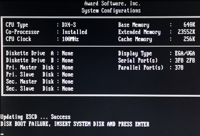
This actually looks fine, but oviously the BIOS is a bit dated and does not know the brand name of the DX4 processor. The generic "DX4-S" printout is normal on older Award BIOS editions with enhanced AMD 486 processors like the AMD 486DX4 and the AMD 5x86. It should not disturb normal operation. As far as I can remember, you get "DX4 100" printed with both the DX4 at 100MHz and the 5x86 at 133MHz. The BIOS always assumes 33MHz * 3 and does auto-config according to 33MHz front side bus clock. I think you will also get "DX4-S @ 100MHz" if you run at 3*40, 3*50MHz or 4*40MHz, so in that case, "auto config" in the chipset setup will tune the chipset to speeds that are known to work well at 33MHz, but might be unreliable at 40MHz. Main takeaway: Don't use auto-config if your bus clock is higher than 33MHz and your processor is faster than 100MHz. Manual config works fine without problems, and most people here on VOGONs are using manual config anyway to push their benchmark scores to the limit.
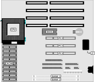
The other day I got this very same board (PCI486 V1-HJ3) with a DX266 on board. When powered up, nothing happens. The ISA diagnostic board reports no post codes, which is a bad sign usually. The PSU is ok because it works with my 386 board. I suspect it may be a hardware issue, but nothing obvious shows up (no cut traces on the back, no shorted pins), except perhaps C42 and C53 that a re a bit swollen. Any suggestion about how to revive this board, please ?
Thanks in advance!
The cache ones are all traced out too and there's essentially 3 links to connect upper address lines of the 2 banks together or directly to some pins on the chipset. I don't yet know the significance of it, but the wrong BIOS definitely recognizes that there's 256KB of cache but will crash. I'll be tracing out how the cache is connected soon. It'll be a great board once there's working cache ~
quicknick wrote:
Hi, congrats on your work! I will be able to provide this next week if you're still interested. I'm out of the country at the moment.
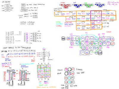
I have actually figured out the way the jumpers work meanwhile so there's actual need to know them anymore with the exception of seeing the actual listed voltages, since I didn't actually measure exactly 3.3V or 3.45 etc. but more in all cases.
Hi!
So, I just happen to have gotten one of these boards and I wonder if the jumpers settings @Tiido posted at some point have been confirmed of corrected.
The reason I'm asking is this:
- The board runs slow and higly unstable, locking up frequently even when I am barely testing it. (FWIW it looks fine and was very clean)
- The sale was advertised as including a Cyrix 486, but the BIOS and utilities I've ran all detect it as an Intel 486 DX4 100. Perhaps the seller swapped the CPU when he agreed to lower the price and my jumpers are now wrong (I' d swear there was a pic with the BIOS showing "Cyrix" that was removed from the ad, but I was looking at so much stuff that I might be wrong...)
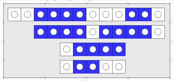
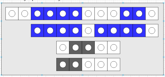
- Lastly, the jumpers came in a layout that does not match what Tiido found back when he worked on his board.
The lowest grey one essentially disables writeback funciton, making a cache flush every time a write happens as it connects Invalidate pin of an Intel/AMD CPU to read/write strobe. For Cyrix the middle pin is SUSPA which the right connection is toward right, where it is pulled up and suspend is disabled that way.
This jumper can make performance very slow, like on some motherboards in writeback mode except there's no dirty bit so they are flushing all the time and bringing performace down.
The second line from below is two jumpers, 123 and 45. 123 handle SMI and HITM pins, for Cyrix in needs to be 12 for mobo SMI to connect to CPU SMI, for Intel/AMD it needs to be 23 for the two to connect.
45 and the neigbhors right below are for L1 WB/WT control. Lower for WT, higher for WT.
I am confident the settings I traced out are correct, unless there are revisions of the board that do change meaning of the jumpers.