VOGONS


Ti4200 x8 (Ti4800) - ASUS V9280S Broken

Topic actions

Reply 60 of 70, by zuldan

User metadata
Rank Oldbie
Rank
Oldbie

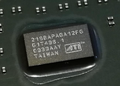
Managed to get MATS going. I just can't figure out how to get it to save the report to a file. Looks like 1 memory chip has failed.

The attachment MATS.JPG is no longer available

Reply 61 of 70, by tehsiggi

User metadata
Rank Member
Rank
Member

Wow! It's coming back alive.. That card sure had a rough time. Given that bith ISLs have been broken.

Haven't used MATS very often unfortunately. But it's the same BGA memory with the same old issues as for the 9700/9800 from team red.

AGP Card Real Power Consumption
AGP Power monitor - diagnostic hardware tool
Graphics card repair collection

Reply 62 of 70, by zuldan

User metadata
Rank Oldbie
Rank
Oldbie
tehsiggi wrote on 2025-11-26, 14:33:

Wow! It's coming back alive.. That card sure had a rough time. Given that bith ISLs have been broken.

Haven't used MATS very often unfortunately. But it's the same BGA memory with the same old issues as for the 9700/9800 from team red.

I’ve worked out how to log to a file so will try that tomorrow. The next thing is to work out which chip is failing. This posts shows how to work it out. https://www.computerbase.de/forum/threads/tut … y-step.2179105/

Hopefully similar chip ordering is used on my older card. I suspect the bad chip is on the back of the card (no heat sinks).

Reply 63 of 70, by tehsiggi

User metadata
Rank Member
Rank
Member

Though I'm currently on vacation, i couldn't help myself and check the schematic for you.

You can see that the Chip has 4 memory channels with 32bits each on page 8 of the schematic. Named FBA to FBD (Frame Buffer A to D). The memory you are using on this card is 32bit memory, meaning that you'll have to have 2 chips per memory channel connected (two ranks). The pages 9-12 show the individual memory ICs and their connection. You can check the chip select pins on the memory chips to figure out if they are rank0 or rank1.

Looking at this, the following mapping appears to me:

  • FBA0 - U804
  • FBA1 - U402
  • FBB0 - U805
  • FBB1 - U404
  • FBC0 - U802
  • FBC1 - U406
  • FBD0 -U803
  • FBD1 - U408

Hope that helps you.. I'll prep some dinner now 😉

AGP Card Real Power Consumption
AGP Power monitor - diagnostic hardware tool
Graphics card repair collection

Reply 64 of 70, by zuldan

User metadata
Rank Oldbie
Rank
Oldbie
tehsiggi wrote on 2025-11-26, 16:04:
Though I'm currently on vacation, i couldn't help myself and check the schematic for you. […]
Show full quote

Though I'm currently on vacation, i couldn't help myself and check the schematic for you.

You can see that the Chip has 4 memory channels with 32bits each on page 8 of the schematic. Named FBA to FBD (Frame Buffer A to D). The memory you are using on this card is 32bit memory, meaning that you'll have to have 2 chips per memory channel connected (two ranks). The pages 9-12 show the individual memory ICs and their connection. You can check the chip select pins on the memory chips to figure out if they are rank0 or rank1.

Looking at this, the following mapping appears to me:

  • FBA0 - U804
  • FBA1 - U402
  • FBB0 - U805
  • FBB1 - U404
  • FBC0 - U802
  • FBC1 - U406
  • FBD0 -U803
  • FBD1 - U408

Hope that helps you.. I'll prep some dinner now 😉

Glad you're on vacation. Enjoy 😀

That will help a lot, thank you. I got the report logging working.

Reply 65 of 70, by zuldan

User metadata
Rank Oldbie
Rank
Oldbie
tehsiggi wrote on 2025-11-26, 16:04:
Though I'm currently on vacation, i couldn't help myself and check the schematic for you. […]
Show full quote

Though I'm currently on vacation, i couldn't help myself and check the schematic for you.

You can see that the Chip has 4 memory channels with 32bits each on page 8 of the schematic. Named FBA to FBD (Frame Buffer A to D). The memory you are using on this card is 32bit memory, meaning that you'll have to have 2 chips per memory channel connected (two ranks). The pages 9-12 show the individual memory ICs and their connection. You can check the chip select pins on the memory chips to figure out if they are rank0 or rank1.

Looking at this, the following mapping appears to me:

  • FBA0 - U804
  • FBA1 - U402
  • FBB0 - U805
  • FBB1 - U404
  • FBC0 - U802
  • FBC1 - U406
  • FBD0 -U803
  • FBD1 - U408

Hope that helps you.. I'll prep some dinner now 😉

So the memory chips are K4D26323RA-GC33. I can only find the following versions. Are cards from this era fussy with memory?

K4D26323RA-GC2A
K4D26323RA-GC36
K4D26323RA-GC28

https://www.aliexpress.com/item/1005010020320681.html

Reply 66 of 70, by dm-

User metadata
Rank Member
Rank
Member

the chip is on the front side, first chip close to agp port.

do the simple reflow. bga flux + heatgun. gentle touch the chip when solder melted, done.

and probably some L filters near vga are knocked off

Reply 67 of 70, by zuldan

User metadata
Rank Oldbie
Rank
Oldbie
dm- wrote on 2025-11-27, 05:13:

the chip is on the front side, first chip close to agp port.

do the simple reflow. bga flux + heatgun. gentle touch the chip when solder melted, done.

and probably some L filters near vga are knocked off

Yep exactly the chip I thought was buggered. Going to pre-heater the board then use a heat gun to reduce shock. The first problem though is the heat sink is glued to the memory. Going to try the freezing trick https://youtube.com/shorts/oV2OrlhY9Bw?si=roSI4sBAN2DSgzHT

I’ll check out the L filters. Thanks!

Reply 68 of 70, by zuldan

User metadata
Rank Oldbie
Rank
Oldbie

Well I got lucky and the heatsinks weren't glued. They had thermal tape.

I've reflowed the memory chip (tapped it gently from the side and it shot back into place). Max temp the chip got to was 245C. Still the same issue 🙁

The attachment IMG_20251129_125358.jpg is no longer available

I did notice some corrosion around the memory chip. So it's possible one of the components around the memory chip is broken or the corrosion went down a via hole OR the memory chip is dead. I checked all the resistors around the memory chip and they are within spec.

The attachment 20240731_073309.JPG is no longer available

Reply 69 of 70, by dm-

User metadata
Rank Member
Rank
Member

that's bad, rusted connections between pcb layers.

remove memory chip and do pin to pin checking with multimeter in diode mode, something is missed here.

Reply 70 of 70, by zuldan

User metadata
Rank Oldbie
Rank
Oldbie
dm- wrote on 2025-11-30, 07:06:

that's bad, rusted connections between pcb layers.

remove memory chip and do pin to pin checking with multimeter in diode mode, something is missed here.

You're right, I should have removed the chip and checked the pin connections.

I've purchased an ultrasonic cleaner (xmas present from wife 😜). Going to see what it can do with this board's corrosion. 5 minutes each side at 60c. I'll then remove the memory chip and check the connections.