VOGONS


PS/2 to Serial Mouse protocol converter

Topic actions

Reply 100 of 125, by sklawz

User metadata
Rank Member
Rank
Member

Hi

feipoa wrote:
sklawz wrote:

However, if you wish to investigate creating a Logitech mouse converter, then please go ahead. I remember seeing some documentation stating that their mice may run at a higher baud rate.

Perhaps when I retire, or when the kids move out.

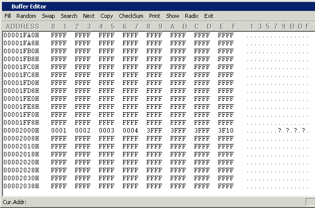
I was able to get Weilei to update their software. I now get 3F10 on 2007H when read back from the PIC (attachment), however when the PIC is placed in the circuit, both LEDs remain active. I'll re-investigate this when the 688's come in.

Whilst that attachment shows 3F10 at 2007 it doesn't show the USERID at 2000-2003 which was previously 0 and more importantly the DEVICEID at 2006 which is read only. It proves nothing.

You can try programming the new hex file here:
http://dev.kewl.org/misc/mouse/pic16f628a.hex

This file now writes 1, 2, 3, 4 to the USERID area. If you test it the perform a full dump it would be useful to see.

Bye

Reply 101 of 125, by feipoa

User metadata
Rank l33t++
Rank
l33t++

USERID matches what you noted. What value should be in 2006H?

Attachments

  • Wellon_USERID.png
    Filename
    Wellon_USERID.png
    File size
    9.93 KiB
    Views
    2185 views
    File license
    Fair use/fair dealing exception

Plan your life wisely, you'll be dead before you know it.

Reply 102 of 125, by sklawz

User metadata
Rank Member
Rank
Member

hi

feipoa wrote:

USERID matches what you noted. What value should be in 2006H?

That looks like what will be programmed and not what was programmed.

Before when you done a dump it showed 1066 at 2006 which is the PIC16F628A device and revision ID.

Bye

Reply 103 of 125, by feipoa

User metadata
Rank l33t++
Rank
l33t++

The image shown directly above is for the read-back PIC file. I checked again.

The dump which showed 1066 at 2006H was before Weilei fixed some aspect of their software to correct the issue with the Config word. In the process, it looks like something else broke. The programmer is not correctly reading from 2006H, but if 2006H is read only, they it should still be at 1066, right?

Is it necessary for proper PIC operation to have 2006H read back correctly from the programmer? Should I hassle Weilei to correct this?

EDIT: I have sent Weilei another e-mail asking them to fix this.

Plan your life wisely, you'll be dead before you know it.

Reply 104 of 125, by sklawz

User metadata
Rank Member
Rank
Member

Hi

feipoa wrote:

The image shown directly above is for the read-back PIC file. I checked again.

The dump which showed 1066 at 2006H was before Weilei fixed some aspect of their software to correct the issue with the Config word. In the process, it looks like something else broke. The programmer is not correctly reading from 2006H, but if 2006H is read only, they it should still be at 1066, right?

Is it necessary for proper PIC operation to have 2006H read back correctly from the programmer? Should I hassle Weilei to correct this?

So far what has been proven is that the software you are using does not work. This correction appears to have corrected nothing and the device is still not being programmed and is not working. Further you are now unable to view the device ID, which at least, was readable before.

I can't speculate further as to why or whether this programmer will ever work or not and it's not really the purpose of this thread after all.

Let's wait until your PIC16F688 devices arrive and you can use your PICKIT1 programmer instead.

Bye.

Reply 105 of 125, by feipoa

User metadata
Rank l33t++
Rank
l33t++

sklawz, does the USERID need to show 0000 0000 0000 0000 for the PIC to function properly? If it shows 0001 0002 0003 0004 or 3FFF 3FFF 3FFF 3FFF, will the PIC still function as intended? I got Weilei to fix the issue with DEVICEID 1066, which it now reads back correctly. The only issue with the 2000-2007 addresses is that the software won't read back 0000 0000 0000 0000, but reads/writes 1, 2, 3, 4 as expected. Instead of 0000, it sees 3FFF.

I am still waiting on the PIC16F688 chips to arrive.

Keropi, did you PIC chips arrive yet? Have you been able to test the circuit?

Plan your life wisely, you'll be dead before you know it.

Reply 106 of 125, by sklawz

User metadata
Rank Member
Rank
Member

LO

feipoa wrote:

sklawz, does the USERID need to show 0000 0000 0000 0000 for the PIC to function properly? If it shows 0001 0002 0003 0004 or 3FFF 3FFF 3FFF 3FFF, will the PIC still function as intended? I got Weilei to fix the issue with DEVICEID 1066, which it now reads back correctly. The only issue with the 2000-2007 addresses is that the software won't read back 0000 0000 0000 0000, but reads/writes 1, 2, 3, 4 as expected. Instead of 0000, it sees 3FFF.

I am still waiting on the PIC16F688 chips to arrive.

The content of the USERID is unimportant for the operation of the micro-controller. For example, it can be utilised for storing a software version, hardware serial number or production code. The value is only available from within an ICSP programmer and not the software running on the micro-controller (12 or 14-bit word architecture).

Bye.

Reply 107 of 125, by feipoa

User metadata
Rank l33t++
Rank
l33t++

Do you happen to have a PICKit? For whatever reason, when I open the PIC16F688 HEX file using the PICKit 1 Classic flash writing program, it indicates 3FFF for all the address fields. Next I try to use MPLAB IDE v8.60, which came with the PICKit 1, to open the ASM file and "build". Immediately, I receive 55 errors, 52 of which may stem from the compiler not being able to locate device.inc, const.inc, and macro.inc. Where can I find these files? They do not appear to be included in the MPASM Suite I have installed.

Plan your life wisely, you'll be dead before you know it.

Reply 108 of 125, by sklawz

User metadata
Rank Member
Rank
Member

Hi

feipoa wrote:

Do you happen to have a PICKit? For whatever reason, when I open the PIC16F688 HEX file using the PICKit 1 Classic flash writing program, it indicates 3FFF for all the address fields. Next I try to use MPLAB IDE v8.60, which came with the PICKit 1, to open the ASM file and "build". Immediately, I receive 55 errors, 52 of which may stem from the compiler not being able to locate device.inc, const.inc, and macro.inc. Where can I find these files? They do not appear to be included in the MPASM Suite I have installed.

I don't have a PICKIT1.

I have no idea why it is unable to read the hex file. There is nothing extraordinary about it.

If you want to build your own hex file then you need the full source which contains those files you mention above. they are in the `include' directory (Src/asm/include/).

Everything can be found in this archive:
http://dev.kewl.org/k8048/k8048-2.13-dev.tar.gz

Alternatively, you may see if this program is able to program the hex file on your pickit-1 (scroll down for windows version):
http://tfc.duke.free.fr/pickit.html

Bye.

EDIT:SPELLING

Reply 109 of 125, by feipoa

User metadata
Rank l33t++
Rank
l33t++

Thank you for the information on usb_pickit 1.6. I am trying it now. I was able to program the chip and it read back "verified", but when I read back the the chip data, it is all 3FFF. Also, my Wellon does not support this particular PIC for programming.

On another note, why does your breadboard setup image not show ST232 Tx1 IN and Tx2 IN connected to PIC16F688 pins RC4 and RC3, respectively? Also, your breadboard image shows serial GND connected to breadboard GND, while the schematic does not indicate this. Are you connecting DB9 GND PIN 5 or shield to breadboard GND? The serial port shield is not grounded on the computer side, so I am just going to connect, both, GND and shield to breadboard GND.

With the PIC16F688, what will be the expected response of the single LED? Mine stays red after applying 5V. I guess this is what happens when 3FFF gets programmed to every address. Maybe the PICKit1 doesn't really support the PIC16F688, although the IDE and specifications claim that it does.

Plan your life wisely, you'll be dead before you know it.

Reply 110 of 125, by feipoa

User metadata
Rank l33t++
Rank
l33t++

Odd, I can read the programmed PIC code back using the Microchip program but not the USB_pickit program. This is what the Microchip program shows for the USB_pickit-programmed PIC,

0000  28BD 3FFF 3FFF 3FFF 28C8 00A5 01A6 01A7 
0008 0BA7 2808 0BA6 2808 0BA5 2808 3400 3EFF
0010 1D03 280F 3400 00A5 3004 200F 0BA5 2814
0018 3400 00A5 3031 200F 0BA5 281A 3400 00A6
0020 300A 2019 0BA6 2820 3400 1003 3008 00A6
0028 01A7 01A8 1C87 3400 0BA8 282A 0BA7 282A
0030 0BA6 282A 1403 3400 1003 3040 00A6 01A7
0038 1887 3400 0BA7 2838 0BA6 2838 1403 3400
0040 00A9 300C 2013 1683 1303 1407 1283 1303
0048 1683 1303 1087 1283 1303 300C 2013 1683
0050 1303 1007 1283 1303 3004 2013 1683 1303
0058 1487 1283 1303 01AA 3008 00A5 2025 1803
0060 28BC 0CA9 1803 286A 1683 1303 1007 1283
0068 1303 2870 1683 1303 1407 1283 1303 0AAA
0070 2034 1803 28BC 0BA5 285E 2025 1803 28BC
0078 0CAA 1C03 2881 1683 1303 1007 1283 1303
0080 2886 1683 1303 1407 1283 1303 2034 1803
0088 28BC 2025 1803 28BC 1683 1303 1407 1283
0090 1303 2034 1803 28BC 2025 1803 28BC 2034
0098 1803 28BC 01A9 2025 1803 28BC 2034 1803
00A0 28BC 3008 00A5 2025 1803 28BC 0CA9 3000
00A8 1807 3080 04A9 2034 1803 28BC 0BA5 28A3
00B0 2025 1803 28BC 2034 1803 28BC 2025 1803
00B8 28BC 2034 1803 28BC 3400 1683 1303 3070
00C0 008F 1D0F 28C1 1283 1303 3000 00A4 0087
00C8 1283 1303 3005 201F 3000 00A3 0085 0824
00D0 3A04 00A4 0087 018B 018C 3007 0099 1683
00D8 1303 018C 3007 0081 0196 0191 303B 0095
00E0 30FF 0085 30F3 0087 1283 1303 0191 0192
00E8 3067 0093 3090 0097 3020 0096 0814 0814
00F0 3090 008B 304D 2131 30F6 2040 1803 28F4
00F8 30FF 2040 1803 28F4 209A 1803 28F4 209A
0100 1803 28F4 30F3 2040 1803 28F4 3014 2040
0108 1803 28F4 30E8 2040 1803 28F4 3000 1A05
0110 3801 1A85 3802 2040 1803 28F4 30E6 1885
0118 30E7 2040 1803 28F4 30F4 2040 1803 28F4
0120 209A 1803 2920 0829 00A0 209A 1803 28F4
0128 0829 00A1 209A 1803 28F4 0829 00A2 2137
0130 2920 1C8C 2931 0095 1C96 2934 0008 1805
0138 2942 1003 1A20 1403 0CA1 1003 1AA0 1403
0140 0CA2 2954 30FF 1A20 06A1 307F 1BA1 00A1
0148 30FF 1A20 06A1 30FF 1AA0 06A2 307F 1BA2
0150 00A2 30FF 1AA0 06A2 0822 3A80 1D03 295B
0158 307F 00A2 295E 30FF 06A2 0AA2 30C0 1820
0160 3820 18A0 3810 1B21 3801 1BA1 3802 1B22
0168 3804 1BA2 3808 2131 0821 393F 3880 2131
0170 0822 393F 3880 2931 3FFF 3FFF 3FFF 3FFF
0178 3FFF 3FFF 3FFF 3FFF 3FFF 3FFF 3FFF 3FFF
0180 3FFF 3FFF 3FFF 3FFF 3FFF 3FFF 3FFF 3FFF

Is this correct? And should there be DEVICEID at 2007H? Program memory doesn't go beyond address 0FF8, but for some reason the USB_PICKit can read the config, which is as follows,

0x2000 = 01
0x2001 = 02
0x2002 = 03
0x2003 = 04
0x2004 = 3FFF
0x2005 = 3FFF
0x2006 = 1186
0x2007 = 30E4

PICkit Programmer checksum = 9217
PICkit Prg+Config checksum = 92fb
PICkit Prgrmr chksm EEData = 00

EDIT due to adding CONFIG code.

Last edited by feipoa on 2013-03-24, 11:05. Edited 2 times in total.

Plan your life wisely, you'll be dead before you know it.

Reply 111 of 125, by feipoa

User metadata
Rank l33t++
Rank
l33t++

When trying to build from source, I get many warnings, but only 4 errors now. The errors are as follows,

Error[113] D:\TEMP\PIC16F688-MOUSE.ASM 119 : Symbol not previously defined (INIT)
Error[113] D:\TEMP\PIC16F688-MOUSE.ASM 121 : Symbol not previously defined (REINIT)
Error[121] D:\TEMP\PIC16F688-MOUSE.ASM 141 : Illegal label (INIT)
Error[121] D:\TEMP\PIC16F688-MOUSE.ASM 155 : Illegal label (REINIT)

Plan your life wisely, you'll be dead before you know it.

Reply 112 of 125, by sklawz

User metadata
Rank Member
Rank
Member

Hi

feipoa wrote:

Thank you for the information on usb_pickit 1.6. I am trying it now. I was able to program the chip and it read back "verified", but when I read back the the chip data, it is all 3FFF. Also, my Wellon does not support this particular PIC for programming.

On another note, why does your breadboard setup image not show ST232 Tx1 IN and Tx2 IN connected to PIC16F688 pins RC4 and RC3, respectively? Also, your breadboard image shows serial GND connected to breadboard GND, while the schematic does not indicate this. Are you connecting DB9 GND PIN 5 or shield to breadboard GND? The serial port shield is not grounded on the computer side, so I am just going to connect, both, GND and shield to breadboard GND.

With the PIC16F688, what will be the expected response of the single LED? Mine stays red after applying 5V. I guess this is what happens when 3FFF gets programmed to every address. Maybe the PICKit1 doesn't really support the PIC16F688, although the IDE and specifications claim that it does.

The pinout is correct on the breadboard. Tx1-in is connected to RC4/TX and Rx2-Out is connected to RA2/INT.

The other pins are unimportant and are `future expansion' 😀

The serial input must be ground using the ground pin and not the shield. The schematic shows the left side as IBM-PC which is taken to include both the serial and power which share a common earth. It is implied.

The LED should be ON when powering the circuit, this is correct. It will toggle off/on every time the circuit is reset by the host computer when probing for a mouse.

Bye

Reply 113 of 125, by sklawz

User metadata
Rank Member
Rank
Member

lo

feipoa wrote:
Odd, I can read the programmed PIC code back using the Microchip program but not the USB_pickit program. This is what the Microc […]
Show full quote

Odd, I can read the programmed PIC code back using the Microchip program but not the USB_pickit program. This is what the Microchip program shows for the USB_pickit-programmed PIC,

0000  28BD 3FFF 3FFF 3FFF 28C8 00A5 01A6 01A7 
0008 0BA7 2808 0BA6 2808 0BA5 2808 3400 3EFF
0010 1D03 280F 3400 00A5 3004 200F 0BA5 2814
0018 3400 00A5 3031 200F 0BA5 281A 3400 00A6
0020 300A 2019 0BA6 2820 3400 1003 3008 00A6
0028 01A7 01A8 1C87 3400 0BA8 282A 0BA7 282A
0030 0BA6 282A 1403 3400 1003 3040 00A6 01A7
0038 1887 3400 0BA7 2838 0BA6 2838 1403 3400
0040 00A9 300C 2013 1683 1303 1407 1283 1303
0048 1683 1303 1087 1283 1303 300C 2013 1683
0050 1303 1007 1283 1303 3004 2013 1683 1303
0058 1487 1283 1303 01AA 3008 00A5 2025 1803
0060 28BC 0CA9 1803 286A 1683 1303 1007 1283
0068 1303 2870 1683 1303 1407 1283 1303 0AAA
0070 2034 1803 28BC 0BA5 285E 2025 1803 28BC
0078 0CAA 1C03 2881 1683 1303 1007 1283 1303
0080 2886 1683 1303 1407 1283 1303 2034 1803
0088 28BC 2025 1803 28BC 1683 1303 1407 1283
0090 1303 2034 1803 28BC 2025 1803 28BC 2034
0098 1803 28BC 01A9 2025 1803 28BC 2034 1803
00A0 28BC 3008 00A5 2025 1803 28BC 0CA9 3000
00A8 1807 3080 04A9 2034 1803 28BC 0BA5 28A3
00B0 2025 1803 28BC 2034 1803 28BC 2025 1803
00B8 28BC 2034 1803 28BC 3400 1683 1303 3070
00C0 008F 1D0F 28C1 1283 1303 3000 00A4 0087
00C8 1283 1303 3005 201F 3000 00A3 0085 0824
00D0 3A04 00A4 0087 018B 018C 3007 0099 1683
00D8 1303 018C 3007 0081 0196 0191 303B 0095
00E0 30FF 0085 30F3 0087 1283 1303 0191 0192
00E8 3067 0093 3090 0097 3020 0096 0814 0814
00F0 3090 008B 304D 2131 30F6 2040 1803 28F4
00F8 30FF 2040 1803 28F4 209A 1803 28F4 209A
0100 1803 28F4 30F3 2040 1803 28F4 3014 2040
0108 1803 28F4 30E8 2040 1803 28F4 3000 1A05
0110 3801 1A85 3802 2040 1803 28F4 30E6 1885
0118 30E7 2040 1803 28F4 30F4 2040 1803 28F4
0120 209A 1803 2920 0829 00A0 209A 1803 28F4
0128 0829 00A1 209A 1803 28F4 0829 00A2 2137
0130 2920 1C8C 2931 0095 1C96 2934 0008 1805
0138 2942 1003 1A20 1403 0CA1 1003 1AA0 1403
0140 0CA2 2954 30FF 1A20 06A1 307F 1BA1 00A1
0148 30FF 1A20 06A1 30FF 1AA0 06A2 307F 1BA2
0150 00A2 30FF 1AA0 06A2 0822 3A80 1D03 295B
0158 307F 00A2 295E 30FF 06A2 0AA2 30C0 1820
0160 3820 18A0 3810 1B21 3801 1BA1 3802 1B22
0168 3804 1BA2 3808 2131 0821 393F 3880 2131
0170 0822 393F 3880 2931 3FFF 3FFF 3FFF 3FFF
0178 3FFF 3FFF 3FFF 3FFF 3FFF 3FFF 3FFF 3FFF
0180 3FFF 3FFF 3FFF 3FFF 3FFF 3FFF 3FFF 3FFF

Is this correct? And should there be DEVICEID at 2007H? Program memory doesn't go beyond address 0FF8, but for some reason the USB_PICKit can read the config, which is as follows,

0x2000 = 01
0x2001 = 02
0x2002 = 03
0x2003 = 04
0x2004 = 3FFF
0x2005 = 3FFF
0x2006 = 1186
0x2007 = 30E4

PICkit Programmer checksum = 9217
PICkit Prg+Config checksum = 92fb
PICkit Prgrmr chksm EEData = 00

EDIT due to adding CONFIG code.

I will check this later when I turn on my R-PI with k8048 programmer attached.

Bye

Reply 114 of 125, by sklawz

User metadata
Rank Member
Rank
Member

lo again

feipoa wrote:
When trying to build from source, I get many warnings, but only 4 errors now. The errors are as follows, […]
Show full quote

When trying to build from source, I get many warnings, but only 4 errors now. The errors are as follows,

Error[113] D:\TEMP\PIC16F688-MOUSE.ASM 119 : Symbol not previously defined (INIT)
Error[113] D:\TEMP\PIC16F688-MOUSE.ASM 121 : Symbol not previously defined (REINIT)
Error[121] D:\TEMP\PIC16F688-MOUSE.ASM 141 : Illegal label (INIT)
Error[121] D:\TEMP\PIC16F688-MOUSE.ASM 155 : Illegal label (REINIT)

You can rename those labels. This source was written to assemble with GPASM. GPASM is an MPASM clone and it would seem slightly incompatible.

You could rename INIT to START and REINIT to RESTART for example.

Bye

EDIT:Changed rename example to something more sensible.

Last edited by sklawz on 2013-03-24, 18:52. Edited 1 time in total.

Reply 115 of 125, by sklawz

User metadata
Rank Member
Rank
Member
feipoa wrote:
Odd, I can read the programmed PIC code back using the Microchip program but not the USB_pickit program. This is what the Microc […]
Show full quote

Odd, I can read the programmed PIC code back using the Microchip program but not the USB_pickit program. This is what the Microchip program shows for the USB_pickit-programmed PIC,

0000  28BD 3FFF 3FFF 3FFF 28C8 00A5 01A6 01A7 
0008 0BA7 2808 0BA6 2808 0BA5 2808 3400 3EFF
0010 1D03 280F 3400 00A5 3004 200F 0BA5 2814
0018 3400 00A5 3031 200F 0BA5 281A 3400 00A6
0020 300A 2019 0BA6 2820 3400 1003 3008 00A6
0028 01A7 01A8 1C87 3400 0BA8 282A 0BA7 282A
0030 0BA6 282A 1403 3400 1003 3040 00A6 01A7
0038 1887 3400 0BA7 2838 0BA6 2838 1403 3400
0040 00A9 300C 2013 1683 1303 1407 1283 1303
0048 1683 1303 1087 1283 1303 300C 2013 1683
0050 1303 1007 1283 1303 3004 2013 1683 1303
0058 1487 1283 1303 01AA 3008 00A5 2025 1803
0060 28BC 0CA9 1803 286A 1683 1303 1007 1283
0068 1303 2870 1683 1303 1407 1283 1303 0AAA
0070 2034 1803 28BC 0BA5 285E 2025 1803 28BC
0078 0CAA 1C03 2881 1683 1303 1007 1283 1303
0080 2886 1683 1303 1407 1283 1303 2034 1803
0088 28BC 2025 1803 28BC 1683 1303 1407 1283
0090 1303 2034 1803 28BC 2025 1803 28BC 2034
0098 1803 28BC 01A9 2025 1803 28BC 2034 1803
00A0 28BC 3008 00A5 2025 1803 28BC 0CA9 3000
00A8 1807 3080 04A9 2034 1803 28BC 0BA5 28A3
00B0 2025 1803 28BC 2034 1803 28BC 2025 1803
00B8 28BC 2034 1803 28BC 3400 1683 1303 3070
00C0 008F 1D0F 28C1 1283 1303 3000 00A4 0087
00C8 1283 1303 3005 201F 3000 00A3 0085 0824
00D0 3A04 00A4 0087 018B 018C 3007 0099 1683
00D8 1303 018C 3007 0081 0196 0191 303B 0095
00E0 30FF 0085 30F3 0087 1283 1303 0191 0192
00E8 3067 0093 3090 0097 3020 0096 0814 0814
00F0 3090 008B 304D 2131 30F6 2040 1803 28F4
00F8 30FF 2040 1803 28F4 209A 1803 28F4 209A
0100 1803 28F4 30F3 2040 1803 28F4 3014 2040
0108 1803 28F4 30E8 2040 1803 28F4 3000 1A05
0110 3801 1A85 3802 2040 1803 28F4 30E6 1885
0118 30E7 2040 1803 28F4 30F4 2040 1803 28F4
0120 209A 1803 2920 0829 00A0 209A 1803 28F4
0128 0829 00A1 209A 1803 28F4 0829 00A2 2137
0130 2920 1C8C 2931 0095 1C96 2934 0008 1805
0138 2942 1003 1A20 1403 0CA1 1003 1AA0 1403
0140 0CA2 2954 30FF 1A20 06A1 307F 1BA1 00A1
0148 30FF 1A20 06A1 30FF 1AA0 06A2 307F 1BA2
0150 00A2 30FF 1AA0 06A2 0822 3A80 1D03 295B
0158 307F 00A2 295E 30FF 06A2 0AA2 30C0 1820
0160 3820 18A0 3810 1B21 3801 1BA1 3802 1B22
0168 3804 1BA2 3808 2131 0821 393F 3880 2131
0170 0822 393F 3880 2931 3FFF 3FFF 3FFF 3FFF
0178 3FFF 3FFF 3FFF 3FFF 3FFF 3FFF 3FFF 3FFF
0180 3FFF 3FFF 3FFF 3FFF 3FFF 3FFF 3FFF 3FFF

Is this correct? And should there be DEVICEID at 2007H? Program memory doesn't go beyond address 0FF8, but for some reason the USB_PICKit can read the config, which is as follows,

0x2000 = 01
0x2001 = 02
0x2002 = 03
0x2003 = 04
0x2004 = 3FFF
0x2005 = 3FFF
0x2006 = 1186
0x2007 = 30E4

PICkit Programmer checksum = 9217
PICkit Prg+Config checksum = 92fb
PICkit Prgrmr chksm EEData = 00

EDIT due to adding CONFIG code.

For comparison:

pi3:~> k14 f
[0000] 28BD 3FFF 3FFF 3FFF 28C8 00A5 01A6 01A7
[0008] 0BA7 2808 0BA6 2808 0BA5 2808 3400 3EFF
[0010] 1D03 280F 3400 00A5 3004 200F 0BA5 2814
[0018] 3400 00A5 3031 200F 0BA5 281A 3400 00A6
[0020] 300A 2019 0BA6 2820 3400 1003 3008 00A6
[0028] 01A7 01A8 1C87 3400 0BA8 282A 0BA7 282A
[0030] 0BA6 282A 1403 3400 1003 3040 00A6 01A7
[0038] 1887 3400 0BA7 2838 0BA6 2838 1403 3400
[0040] 00A9 300C 2013 1683 1303 1407 1283 1303
[0048] 1683 1303 1087 1283 1303 300C 2013 1683
[0050] 1303 1007 1283 1303 3004 2013 1683 1303
[0058] 1487 1283 1303 01AA 3008 00A5 2025 1803
[0060] 28BC 0CA9 1803 286A 1683 1303 1007 1283
[0068] 1303 2870 1683 1303 1407 1283 1303 0AAA
[0070] 2034 1803 28BC 0BA5 285E 2025 1803 28BC
[0078] 0CAA 1C03 2881 1683 1303 1007 1283 1303
[0080] 2886 1683 1303 1407 1283 1303 2034 1803
[0088] 28BC 2025 1803 28BC 1683 1303 1407 1283
[0090] 1303 2034 1803 28BC 2025 1803 28BC 2034
[0098] 1803 28BC 01A9 2025 1803 28BC 2034 1803
[00A0] 28BC 3008 00A5 2025 1803 28BC 0CA9 3000
[00A8] 1807 3080 04A9 2034 1803 28BC 0BA5 28A3
[00B0] 2025 1803 28BC 2034 1803 28BC 2025 1803
[00B8] 28BC 2034 1803 28BC 3400 1683 1303 3070
[00C0] 008F 1D0F 28C1 1283 1303 3000 00A4 0087
[00C8] 1283 1303 3005 201F 3000 00A3 0085 0824
[00D0] 3A04 00A4 0087 018B 018C 3007 0099 1683
[00D8] 1303 018C 3007 0081 0196 0191 303B 0095
[00E0] 30FF 0085 30F3 0087 1283 1303 0191 0192
[00E8] 3067 0093 3090 0097 3020 0096 0814 0814
[00F0] 3090 008B 304D 2131 30F6 2040 1803 28F4
[00F8] 30FF 2040 1803 28F4 209A 1803 28F4 209A
[0100] 1803 28F4 30F3 2040 1803 28F4 3014 2040
[0108] 1803 28F4 30E8 2040 1803 28F4 3000 1A05
[0110] 3801 1A85 3802 2040 1803 28F4 30E6 1885
[0118] 30E7 2040 1803 28F4 30F4 2040 1803 28F4
[0120] 209A 1803 2920 0829 00A0 209A 1803 28F4
[0128] 0829 00A1 209A 1803 28F4 0829 00A2 2137
[0130] 2920 1C8C 2931 0095 1C96 2934 0008 1805
[0138] 2942 1003 1A20 1403 0CA1 1003 1AA0 1403
[0140] 0CA2 2954 30FF 1A20 06A1 307F 1BA1 00A1
[0148] 30FF 1A20 06A1 30FF 1AA0 06A2 307F 1BA2
[0150] 00A2 30FF 1AA0 06A2 0822 3A80 1D03 295B
[0158] 307F 00A2 295E 30FF 06A2 0AA2 30C0 1820
[0160] 3820 18A0 3810 1B21 3801 1BA1 3802 1B22
[0168] 3804 1BA2 3808 2131 0821 393F 3880 2131
[0170] 0822 393F 3880 2931 3FFF 3FFF 3FFF 3FFF

pi3:~> k14 c
[2007] [CONFIG] 30E4
[2008] [CALIB] 24F8

[FCMEN] Fail-safe clock monitor disabled

Brown-out reset selection:
[BOR] Disabled

[CPD] Data memory code protection off

Show last 24 lines
[CP] Program memory code protection off

[MCLRE] MCLR enabled

[PWRTE] Power-up timer enabled

[WDT] Watchdog timer disabled

Oscillator selection:
[INTOSCIO] 100 NO CLKOUT

pi3:~> k14 i
[0000] [PROGRAM] 1000 WORDS
[2000] [USERID0] 0001 .
[2001] [USERID1] 0002 .
[2002] [USERID2] 0003 .
[2003] [USERID3] 0004 .
[2004] [RESERVED] 3FFF .
[2005] [RESERVED] 3FFF .
[2006] [DEVICEID] 1186 DEV:1180 (8C) REV:6 PIC16F688
[2007] [CONFIG] 30E4
[2008] [CALIB] 24F8
[2100] [DATA] 0100 BYTES

From what I can see, your chip is ready to go.

Just wire it up and it should work. Use MOUSE.COM in MSDOS to test it, it's easier.

Bye

Reply 116 of 125, by feipoa

User metadata
Rank l33t++
Rank
l33t++
sklawz wrote:

The serial input must be ground using the ground pin and not the shield. The schematic shows the left side as IBM-PC which is taken to include both the serial and power which share a common earth. It is implied.

I personally wouldn't leave pins requiring connection as "implied". If pin 5 of the RS-232 cable needs to be connected to GND for proper operation, I would probably draw in the pin connection on the schematic. I don't think anyone else on the forum who decides to wire up the circuit based on the schematic image would think to connect RS-232 pin 5 to GND. For example, I did not think to connect RS-232 GND pin to circuit GND when testing the previous PIC16F628A microcontroller. Are there any other implied connections we should know about?

It is also customary to bond your RS-232 shield to GND, otherwise the cable shield is not being utilised. For anyone else who wires this up, ensure that your cable shield is connected to GND only at one end of the cable, otherwise you've created a ground loop.

sklawz wrote:

Tx1-in is connected to RC4/TX and Rx2-Out is connected to RA2/INT.

The other pins are unimportant and are `future expansion' :-)

For anyone else who is following this thread, pins 10 and 12 of the MAX232 and pins 5 and 7 of the PIC do not need to be connected (at this time?).

sklawz wrote:

From what I can see, your chip is ready to go.

I had quickly tested it with a reboot in XP, but it didn't work. I'll need to mess around with MOUSE.COM when I have access to a DOS or floppy-connected computer. The LED does light up and cycles with the momentary push button. I'll also try to recompile when I have a moment.

Plan your life wisely, you'll be dead before you know it.

Reply 117 of 125, by sklawz

User metadata
Rank Member
Rank
Member

Hi

feipoa wrote:
I personally wouldn't leave pins requiring connection as "implied". If pin 5 of the RS-232 cable needs to be connected to GND f […]
Show full quote
sklawz wrote:

The serial input must be ground using the ground pin and not the shield. The schematic shows the left side as IBM-PC which is taken to include both the serial and power which share a common earth. It is implied.

I personally wouldn't leave pins requiring connection as "implied". If pin 5 of the RS-232 cable needs to be connected to GND for proper operation, I would probably draw in the pin connection on the schematic. I don't think anyone else on the forum who decides to wire up the circuit based on the schematic image would think to connect RS-232 pin 5 to GND. For example, I did not think to connect RS-232 GND pin to circuit GND when testing the previous PIC16F628A microcontroller. Are there any other implied connections we should know about?

It is also customary to bond your RS-232 shield to GND, otherwise the cable shield is not being utilised. For anyone else who wires this up, ensure that your cable shield is connected to GND only at one end of the cable, otherwise you've created a ground loop.

sklawz wrote:

Tx1-in is connected to RC4/TX and Rx2-Out is connected to RA2/INT.

The other pins are unimportant and are `future expansion' 😀

For anyone else who is following this thread, pins 10 and 12 of the MAX232 and pins 5 and 7 of the PIC do not need to be connected (at this time?).

sklawz wrote:

From what I can see, your chip is ready to go.

I had quickly tested it with a reboot in XP, but it didn't work. I'll need to mess around with MOUSE.COM when I have access to a DOS or floppy-connected computer. The LED does light up and cycles with the momentary push button. I'll also try to recompile when I have a moment.

I get what you are talking about but this schematic is for an internal device powered by the floppy power connector.

If you decide to build a device outside of the IBM PC labelled on the left hand side of the schematic then adjust as appropriate.

Bye.

Reply 118 of 125, by SquallStrife

User metadata
Rank l33t
Rank
l33t

RISE FROM YOUR GRAVE</altered beast>

😜

If I were to build this, are the HEX and schematic files in the initial post still the "latest" versions?

VogonsDrivers.com | Link | News Thread

Reply 119 of 125, by sklawz

User metadata
Rank Member
Rank
Member

lo

all files found under "UPDATE (4th March 2013" are the last developed
versions of what was available.

since that project was created, the PIC programmer has been updated
for use with the R-PI and a breadboard. this opens up the possibility of
utilising more modern PICMicros which may be easier to obtain and
could be cheaper. you will need to port the code to any other PICMicro
unless I have the urge to do so myself.

Bye.

UPDATE: The PIC programmer referred to above, is found here:
http://dev.kewl.org/k8048/Doc/