VOGONS


Wading slowly into the 486 waters

Topic actions

Reply 60 of 72, by clueless1

User metadata
Rank l33t
Rank
l33t

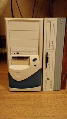
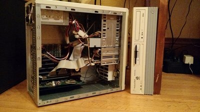
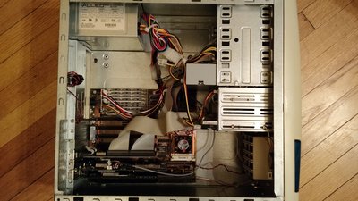
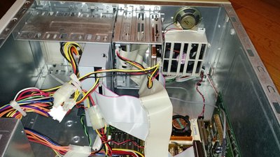
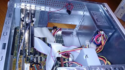
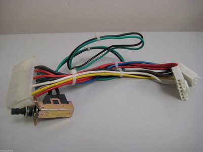
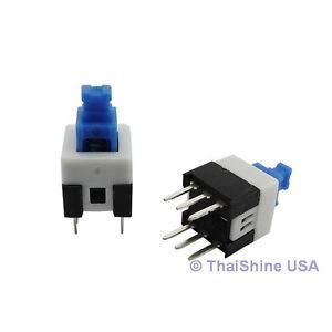
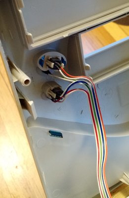
Some good news! Those little 8mm self-latching switches I ordered a few posts up (thanks for the idea TheMobRules) were a perfect drop-in replacement for the existing switches on the front of my case. I took a spare jumper wire, soldered one switch to it, plugged it into Reset button, plugged the other into the turbo header, and poof! My reset button becomes a turbo button! Did the same with the power switch coming off my AT-ATX power supply adapter. So now I can close up my case finally. 😀 Power button=power button; reset button=turbo button. Sweet! Still no I/O shield, but I don't care about that, as I can't see it. 😉

The more I learn, the more I realize how much I don't know.
OPL3 FM vs. Roland MT-32 vs. General MIDI DOS Game Comparison
Let's benchmark our systems with cache disabled
DOS PCI Graphics Card Benchmarks

Reply 61 of 72, by brostenen

User metadata
Rank l33t++
Rank
l33t++

Have given that shield some thoughts on how to make.
If you cut out some vinyl/plastic that fits on the outside of a random shield, and bore a hole in the right place?

Don't eat stuff off a 15 year old never cleaned cpu cooler.
Those cakes make you sick....

My blog: http://to9xct.blogspot.dk
My YouTube: https://www.youtube.com/user/brostenen

001100 010010 011110 100001 101101 110011

Reply 62 of 72, by clueless1

User metadata
Rank l33t
Rank
l33t
brostenen wrote:

Have given that shield some thoughts on how to make.
If you cut out some vinyl/plastic that fits on the outside of a random shield, and bore a hole in the right place?

Someone mentioned using clear plastic from something like an ice cream tub lid. That lets you position the hole easy because you can see through it. Then after cutting the hole, either paint it silver or cover it in aluminum foil. I probably won't do this though, because I'm hopeful to come across a real AT 486 case soon (a friend says he may have some NIB in his storage, and I am waiting for him to find time to check).

The more I learn, the more I realize how much I don't know.
OPL3 FM vs. Roland MT-32 vs. General MIDI DOS Game Comparison
Let's benchmark our systems with cache disabled
DOS PCI Graphics Card Benchmarks

Reply 64 of 72, by brostenen

User metadata
Rank l33t++
Rank
l33t++

Uhh.... This clear plastic makes me think of a possible way of doing an easter egg artwork kind of thingy. 🤣

Don't eat stuff off a 15 year old never cleaned cpu cooler.
Those cakes make you sick....

My blog: http://to9xct.blogspot.dk
My YouTube: https://www.youtube.com/user/brostenen

001100 010010 011110 100001 101101 110011

Reply 65 of 72, by clueless1

User metadata
Rank l33t
Rank
l33t

Here is the final build.

486-0.jpg
Filename
486-0.jpg
File size
879.27 KiB
Views
816 views
File comment
486 on the left. Packard Bell on the right is my Pentium Overdrive 200MMX
File license
Fair use/fair dealing exception
486-2.jpg
Filename
486-2.jpg
File size
1.21 MiB
Views
816 views
File license
Fair use/fair dealing exception
486-3.jpg
Filename
486-3.jpg
File size
1.15 MiB
Views
816 views
File license
Fair use/fair dealing exception
486-4.jpg
Filename
486-4.jpg
File size
1.45 MiB
Views
816 views
File license
Fair use/fair dealing exception
486-5.jpg
Filename
486-5.jpg
File size
1.61 MiB
Views
816 views
File license
Fair use/fair dealing exception

The more I learn, the more I realize how much I don't know.
OPL3 FM vs. Roland MT-32 vs. General MIDI DOS Game Comparison
Let's benchmark our systems with cache disabled
DOS PCI Graphics Card Benchmarks

Reply 66 of 72, by clueless1

User metadata
Rank l33t
Rank
l33t

I forgot to take pics of the switches after I modified them, but basically I cut the green and black wires to remove the big mechanical power switch off of the AT-ATX PSU adapter.

s-l1600.jpg
Filename
s-l1600.jpg
File size
100.76 KiB
Views
814 views
File comment
ebay photo
File license
Fair use/fair dealing exception

I soldered the green and black wires to the latching power switch.

s-l300.jpg
Filename
s-l300.jpg
File size
6.95 KiB
Views
814 views
File comment
latching 8mm switch
File license
Fair use/fair dealing exception

I used the existing momentary switch as a template. So the green wire went on the upper left pin and the black wire went on the pin right below the green. To orient, there is a little hole on the bottom of the switch. Hold the switch so the hole is at the top. Green is on top left pin, black on the middle left pin. Once the soldering is complete, just replace the existing case switch with the new one. There are two clips on my case that hold it in place.

power_inside.jpg
Filename
power_inside.jpg
File size
579.96 KiB
Views
814 views
File license
Fair use/fair dealing exception

I did the same thing for the Reset button below the power button. I got a spare jumper wire from another case and soldered to the latching switch in the same orientation (colored wire upper left, white wire middle left). Dropped the switch into the reset button location, plugged the jumper into the turbo switch header on the motherboard.

Edit: just to note, now when you push the power button on the front of the case, the button stays in a recessed position due to it being a latching switch. Same with the reset button. It stays pushed in when you engage turbo.

The more I learn, the more I realize how much I don't know.
OPL3 FM vs. Roland MT-32 vs. General MIDI DOS Game Comparison
Let's benchmark our systems with cache disabled
DOS PCI Graphics Card Benchmarks

Reply 68 of 72, by clueless1

User metadata
Rank l33t
Rank
l33t
gdjacobs wrote:

Polarity won't matter for the switch.

Good to know. Does it matter which pins? I think they both have to be on the same side but does it matter which of the three pins?

The more I learn, the more I realize how much I don't know.
OPL3 FM vs. Roland MT-32 vs. General MIDI DOS Game Comparison
Let's benchmark our systems with cache disabled
DOS PCI Graphics Card Benchmarks

Reply 69 of 72, by Nipedley

User metadata
Rank Member
Rank
Member

The upper and bottom pins are connected to the middle (common) pin when the switch is either 'in' or 'out' (on a latching switch). The two sides are electically isolated from each other, so you can have one switched between top and bottom on the left side and another switched between top and bottom on the right side.

So for example push and it latches in, top and middle pins are electrically connected, push and it pops back out, bottom and middle pins are electrically connected

Looking good! I'm super jealous of the Pentium MMX machine you have there too!

Reply 70 of 72, by clueless1

User metadata
Rank l33t
Rank
l33t
Nipedley wrote:

The upper and bottom pins are connected to the middle (common) pin when the switch is either 'in' or 'out' (on a latching switch). The two sides are electically isolated from each other, so you can have one switched between top and bottom on the left side and another switched between top and bottom on the right side.

So for example push and it latches in, top and middle pins are electrically connected, push and it pops back out, bottom and middle pins are electrically connected

Looking good! I'm super jealous of the Pentium MMX machine you have there too!

Thanks for the explanation on the switch!

Here's some more photos of the Pentium MMX machine, including some lovely internal shots.
Souped up Packard Bell
I really like having it on my desk with the monitor on top, but it takes up too much room, so I moved it to the floor. 🙁

The more I learn, the more I realize how much I don't know.
OPL3 FM vs. Roland MT-32 vs. General MIDI DOS Game Comparison
Let's benchmark our systems with cache disabled
DOS PCI Graphics Card Benchmarks

Reply 71 of 72, by gdjacobs

User metadata
Rank l33t++
Rank
l33t++

If you're ever in doubt as to which pins are normally open or normally closed, always have a multimeter around.

All hail the Great Capacitor Brand Finder

Reply 72 of 72, by clueless1

User metadata
Rank l33t
Rank
l33t
h-a-l-9000 wrote:

It's not a grounding problem - at the latest when you tighten the screw for the slot plate it makes contact with the case and thus is grounded. The metal down there is electrically same as the rest of the case.

You have cracked solder joints, broken traces, corroded contacts or something along these lines - the little force caused by the bent plates will put it back to operational state. This is no reliable fix though.

The mainboard or affected expansion card have to be considered trash unless you find and fix the cause.

Well, I started having this issue again, where I'd make an adjustment in the case, and it would stop posting. I thought I'd solved it earlier, then your comments above made me think twice. After about an hour of troubleshooting today, it turns out it was an issue with the IDE cable. I have to master/slave my hdd and optical drive, and the cable I was using was oriented such that I had to twist the middle (slave) connector. Something was going on there, either a bad cable, or intermittent disconnecting when I'd make adjustments in the case. Regardless, I swapped the IDE cable out with one that did not force me to twist the slave connector, and that solved the problem.

I literally spent most of my time making one connection, turning the system on, verifying it posted, turning off, making another connection, etc. I was able to reliably reproduce the issue every time I plugged the IDE cable into the controller card. I'd disconnect, it would post. Reconnect, not post. So hopefully this issue is behind me 100% now!

The more I learn, the more I realize how much I don't know.
OPL3 FM vs. Roland MT-32 vs. General MIDI DOS Game Comparison
Let's benchmark our systems with cache disabled
DOS PCI Graphics Card Benchmarks