VOGONS


First post, by dionb

User metadata
Rank l33t++
Rank
l33t++

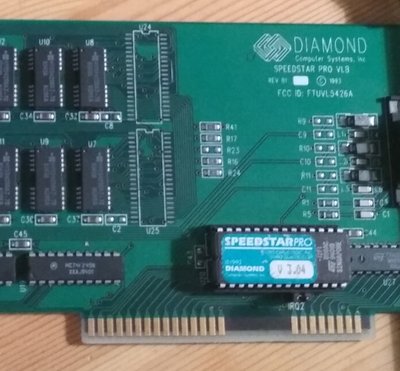
Yesterday I picked up a Diamond Speedstar Pro VLB card. Nothing too special, Cirrus Logic CL-GD5428 chip with 1MB. Most pics show it populated with 2x 40-pin 4Mbit SOJ chips, but mine has 8x 20-pin 1Mbit chips - with the locations for the 40-pin chips empty and enticing.

GD5428 should support 2MB, and a 2MB mid-rage VLB card is a lot more interesting than a 1MB one. So I want to add those two chips. Finding 256Kx16 FPM 70ns DRAM is easy enough, but there's more that needs populating on the PCB. There's a (filter?) capacitor next to each RAM chip. The eight for the 20-pin chips are already in place, the two for the 40-pin chips aren't. Unfortunately I can't figure out what rating I should use.

Here's my card:

speedstar_pro_20.jpg
Filename
speedstar_pro_20.jpg
File size
189.93 KiB
Views
1109 views
File license
Fair use/fair dealing exception

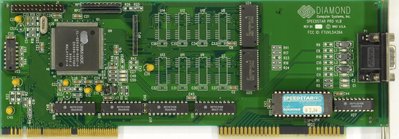
And here's one with the 40-pin chips in place:

755_diamond_speedstar_pro_rev.b1_top_hq.jpg
Filename
755_diamond_speedstar_pro_rev.b1_top_hq.jpg
File size
312.67 KiB
Views
1109 views
File license
Fair use/fair dealing exception

C2 and C8 are the locations I suspect I need to do something with.

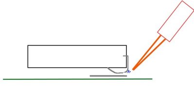
Two little blobs. Either my eyes are going (quite likely actualy) or there's no code on them. Would a 100nF SMD cap like X7R-G0603 work here?

Reply 1 of 25, by keropi

User metadata
Rank l33t++
Rank
l33t++

these are filtering caps so 100nf ones will work fine 😎

🎵 🎧 PCMIDI MPU , OrpheusII , Action Rewind , Megacard and 🎶GoldLib soundcard website

Reply 2 of 25, by dionb

User metadata
Rank l33t++
Rank
l33t++
keropi wrote:

these are filtering caps so 100nf ones will work fine 😎

Great, thanks for the confirmation - I'll use my surplus from a previous project and update once the RAM chips are in 😀

Reply 3 of 25, by dionb

User metadata
Rank l33t++
Rank
l33t++

Update: chips arrived, the caps were easy (despite being too small for the pads), but this was my first attempt at soldering SOJ SMD, and I obviously haven't figured it out yet... don't think I damaged anything, but certainly didn't solder anything either. To be continued once I figure out how.

Reply 4 of 25, by keropi

User metadata
Rank l33t++
Rank
l33t++

align the chip and tap 2 opposite edges to keep it in place, just use some 0.5mm or less solder wire and a fine tip - try and put solder on the crevice the pad and soj leg creates while keeping the iron at an angle so the tip kinda enters there , heat both surfaces and then you introduce some solder... can't explain it better but it will work just fine , made this crude drawing 🤣 🤣 🤣

e0vXvQJl.png

maybe this helps a little 😵
these were meant to be soldered with hot-air means but you can also do it with an iron if you have a little practice

🎵 🎧 PCMIDI MPU , OrpheusII , Action Rewind , Megacard and 🎶GoldLib soundcard website

Reply 5 of 25, by gdjacobs

User metadata
Rank l33t++
Rank
l33t++

I prepare the pads with a wee bit of solder first (just enough to get them wet), then place the component. Heat the first pad until the component flows into it, then quickly heat the other side so it flows in as well. Hold your iron the way Keropi shows so you can transfer some heat to the component in addition to the pad. You can't have too much solder on either pad to start or the cap will be held up on one side.

Once the component is in place and held down, complete the joint. Add a small amount of solder so you have a nice indented fillet from the end of the cap to the rest of the pad then do the same on the other side. This will provide a complete mechanical and electrical junction.

Visually, a perfect joint looks something like this:
images?q=tbn:ANd9GcS_nfaRJyj4eaRhzRDbQu1EltoKbEAvklshPzHQlAOjnnPro8_I6A&s

All hail the Great Capacitor Brand Finder

Reply 6 of 25, by dionb

User metadata
Rank l33t++
Rank
l33t++

I get that, that's what I've managed in the past with SMD (well, not as pretty as the 'perfect' joint, but usable). Issue here is that the pad is completely under the chip, not sticking out at all (see the second photo in the topicstart), so I basically can't reach it to heat it, so the solder sticks to the side of the leg and not to the pad.

soj_soldering_issue.jpg
Filename
soj_soldering_issue.jpg
File size
15.9 KiB
Views
1004 views
File license
Fair use/fair dealing exception

Only way I can get it to stick is to flood it with so much solder that it bridges multiple legs. As soon as I remove that surplus solder, it unsticks again from the pad.

Reply 7 of 25, by keropi

User metadata
Rank l33t++
Rank
l33t++

have the card at an angle there must be some visible pad/leg area you can work there

🎵 🎧 PCMIDI MPU , OrpheusII , Action Rewind , Megacard and 🎶GoldLib soundcard website

Reply 9 of 25, by Anonymous Coward

User metadata
Rank l33t
Rank
l33t

Not sure how many times I can repeat this. 2MB on a 5428 or 5429 is borderline useless. Please prove me wrong, but all it bought me was a few extra interlaced modes. In my opinion, it's seriously not worth the effort. Get a 5434 if you really want 2MB.

"Will the highways on the internets become more few?" -Gee Dubya
V'Ger XT|Upgraded AT|Ultimate 386|Super VL/EISA 486|SMP VL/EISA Pentium

Reply 10 of 25, by dionb

User metadata
Rank l33t++
Rank
l33t++
gdjacobs wrote:

If the pad is completely hidden, you might be using the wrong component series.

Doubt it, take a look at the pic from the VGA museum showing the card fitted with these chips, no pads visible there either.

Anonymous Coward wrote:

Not sure how many times I can repeat this. 2MB on a 5428 or 5429 is borderline useless. Please prove me wrong, but all it bought me was a few extra interlaced modes. In my opinion, it's seriously not worth the effort. Get a 5434 if you really want 2MB.

Fully aware I'm not getting anymore than interlaced modes I won't be using anyway, and that these 542x are probably the least interesting cards to upgrade to 2MB as a consequence. That's precisely why I'm doing this with this card: it's as expendable as any VLB card will ever be. I have another functionally identical 1MB GD5428 already (just no pads on that for the second MB).

My goal with this card is to get confident enough with soldering these things that I'm willing to risk the same work on some more interesting cards. I have two Voodoo2 8MB cards for starters 😉

Reply 11 of 25, by gdjacobs

User metadata
Rank l33t++
Rank
l33t++

Looking at the pictures, when properly aligned you will have perhaps a third of the pad exposed. The caps shown have been installed with nice even fillets.

All hail the Great Capacitor Brand Finder

Reply 12 of 25, by maxtherabbit

User metadata
Rank l33t
Rank
l33t
gdjacobs wrote:
I prepare the pads with a wee bit of solder first (just enough to get them wet), then place the component. Heat the first pad un […]
Show full quote

I prepare the pads with a wee bit of solder first (just enough to get them wet), then place the component. Heat the first pad until the component flows into it, then quickly heat the other side so it flows in as well. Hold your iron the way Keropi shows so you can transfer some heat to the component in addition to the pad. You can't have too much solder on either pad to start or the cap will be held up on one side.

Once the component is in place and held down, complete the joint. Add a small amount of solder so you have a nice indented fillet from the end of the cap to the rest of the pad then do the same on the other side. This will provide a complete mechanical and electrical junction.

Visually, a perfect joint looks something like this:
images?q=tbn:ANd9GcS_nfaRJyj4eaRhzRDbQu1EltoKbEAvklshPzHQlAOjnnPro8_I6A&s

That pic arouses me

Reply 13 of 25, by gdjacobs

User metadata
Rank l33t++
Rank
l33t++
maxtherabbit wrote:

That pic arouses me

I thought it was pretty sexy work, myself.

All hail the Great Capacitor Brand Finder

Reply 14 of 25, by treeman

User metadata
Rank Oldbie
Rank
Oldbie

on mobile phone pcb repair where the smd completely covers the pads or is in a tight place I tin the pads with some leaded solder, dab a bit of flux on the pads, stick the smd on with tweezers then gently blow some 380C hot air on the lowest air pressure.
Once the solder on the pads melts the smd chips align into place and a good joint is created.

Only problem here is this is 20+ year old tech will it take that stress?

Reply 15 of 25, by gdjacobs

User metadata
Rank l33t++
Rank
l33t++

For QFN and such, yes, best practice is to use reflow or hot air depending on the situation. If it has a central heatsink, the surface tension of the solder will pull it into position in a pretty dramatic fashion.

All hail the Great Capacitor Brand Finder

Reply 16 of 25, by cyclone3d

User metadata
Rank l33t++
Rank
l33t++

It is pretty sweet using a hot air rework station and watching the SMD components just pop into place once the solder melts.

Yamaha modified setupds and drivers
Yamaha XG repository
YMF7x4 Guide
Aopen AW744L II SB-LINK

Reply 18 of 25, by yawetaG

User metadata
Rank Oldbie
Rank
Oldbie
dionb wrote:

Something tells me I'm buying a hot air gun for this.

Hot air soldering station. Not a hot air gun, if by "hot air gun" you mean the tool that can heat a large surface, because using that on a circuit board can be a good way to quickly strip it of all components. 🤣 😵

Reply 19 of 25, by gdjacobs

User metadata
Rank l33t++
Rank
l33t++
dionb wrote:

Something tells me I'm buying a hot air gun for this.

By all means, get one if you want. It's hardly required for some simple caps, though.

All hail the Great Capacitor Brand Finder